COMMERCIAL GAS WATER HEATERS SERVICE HANDBOOK HIGH EFFICIENCY COMMERCIAL GAS SERIES FOR MODELS: • • • • • • • • HCG-60T120 AHCG-60T120 HCG-100T150 AHCG-100T150 HCG-100T199 AHCG-100T199 HCG-100T250 AHCG-100T250 PRINTED 0508 1 198153-000
High-Efficiency Commercial Gas Series - Service Manual TABLE OF CONTENTS INTRODUCTION......................................................................................................................................................................2 QUALIFICATIONS....................................................................................................................................................................2 TOOLS REQUIRED.................................................................
High-Efficiency Commercial Gas Series - Service Manual INTRODUCTION The service manual is designed to aid in servicing and troubleshooting High-Efficiency Commercial Gas Series water heaters in the field. Duplication or reproduction of this manual is forbidden without the express written authorization from the manufacturer. The information contained in this manual is designed to answer commonly faced situations encountered in the operation of this product line and is not meant to be all inclusive.
High-Efficiency Commercial Gas Series - Service Manual TOOLS REQUIRED ● ● ● ● ● ● ELECTRICAL MULTIMETER CAPABLE OF MEASURING CONTINUITY/ OHMS, AC & DC VOLTS, AMPERES, MICROAMPERES, MILLIVOLTS, and FREQUENCY(Hz) ○ UEi Model DL289 or equivalent DIGITAL MANOMETER + 60” W. C. in .01” increments Note: A digital manometer is required for testing pressure switches and can replace a gas pressure gauge, draft gauge or slack tube manometer for checking gas pressure.
High-Efficiency Commercial Gas Series - Service Manual GENERAL INFORMATION INSTALLATION REQUIREMENTS FOR THE COMMONWEALTH OF MASSACHUSETTS For all side wall terminated, horizontally vented power vent, direct vent, and power direct vent gas fueled water heaters installed in every dwelling, building or structure used in whole or in part for residential purposes, including those owned or operated by the Commonwealth and where the side wall exhaust vent termination is less than seven (7) feet above finished gra
High-Efficiency Commercial Gas Series - Service Manual GAS PRESSURES – 120 and 150 KBtu/hr MODELS ADJUSTMENT PROCEDURE: GAS PRESSURE 120 AND 150 MODELS CHECKING THE FIRING RATE Verify supply gas pressure is within the requirements given in the Instruction Manual that came with the water heater and shown in the table on page 4 prior to start up. b. Use this formula to “clock” the meter. Be sure other gas consuming appliances are not operating during this interval. a.
High-Efficiency Commercial Gas Series - Service Manual GAS VALVE 120 KBtu/hr MODEL The gas control valve on the 120 KBtu/hr model has a built in adjustable pressure regulator. The adjustment screw is accessed by removing the cap screw market regulator in the illustration. Inlet gas pressure may be read at the inlet pressure tap only if the manual shut off valve (gas cock) is in the “ON” position.
High-Efficiency Commercial Gas Series - Service Manual GAS PRESSURES 199 and 250 KBtu/hr MODELS HIGH ALTITUDE INSTALLATION ADJUSTMENT PROCEDURE: GAS PRESSURE 199 AND 250 MODELS The 199 and 250 models are suitable for installation up to 10,100 feet above sea level with no adjustments. GAS ORIFICE IMPORTANT NOTE The 199 and 250 models do not have a natural gas orifice. A .230” orifice is used on LP gas models.
High-Efficiency Commercial Gas Series - Service Manual GAS VALVE 199 and 250 KBtu/hr MODELS Pressure readings may be taken on the gas valve by connecting a manometer to the pressure ports on the valve. The manifold pressure on this valve is 0”w.c. (0kPa) when the water heater is running. Refer to the gas pressure chart on page 4. Note: Manometer tubing shown is not supplied with the water heater. WARNING: Do not attempt adjustments on this gas valve.
High-Efficiency Commercial Gas Series - Service Manual VENTING TABLES Maximum equivalent feet of intake air and vent pipe using 3” PVC is 50 feet (15.2m). Equivalent feet must include any 90° elbows (two 45° elbows equal one 90° elbow). Three inch diameter 90° elbows are equivalent to 5' (1.5m) of pipe. Maximum equivalent feet of intake and vent pipe using 4” PVC is 120 feet (36.6m). Equivalent feet must include any 90° elbows (two 45° elbows equal one 90° elbow).
High-Efficiency Commercial Gas Series - Service Manual VENTING - ALL MODELS – SINGLE PIPE POWER VENT – USING ROOM AIR MINIMUM 18 INCHES (46 CM) MINIMUM 18 INCHES (46 CM) Technical Literature Department 10 Ashland City, Tennessee © 2008 Servicing should only be performed by a Qualified Service Agent
High-Efficiency Commercial Gas Series - Service Manual VENTING – ALL MODELS – TWO PIPE DIRECT VENT – USING OUTSIDE AIR MINIMUM 18 INCHES (46 CM) MINIMUM 18 INCHES (46 CM) Technical Literature Department 11 Ashland City, Tennessee © 2008 Servicing should only be performed by a Qualified Service Agent
High-Efficiency Commercial Gas Series - Service Manual VENT / INTAKE AIR TERMINATIONS WHEN LOCATING THE VENT AND INTAKE AIR TERMINATIONS ON A SIDEWALL, THE FOLLOWING SPECIFICATIONS PERTAINING TO LOCATION AND CLEARANCES MUST BE FOLLOWED. 1. The intake vent terminal and the exhaust vent terminal must terminate on the same exterior wall and must be located at a minimum of 24" (61cm) from the vertical centerline of the exhaust vent terminal (see Figure 9).
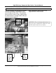
High-Efficiency Commercial Gas Series - Service Manual DIRECT VENT INSTALLATIONS The intake air connection on the water heater contains a mesh screen to prevent large particles from entering the blower. WHEN THE WATER HEATER IS INSTALLED DIRECT VENT (TWO PIPES), THE BALANCE PLATE AND MESH SCREEN MUST BE REMOVED BEFORE GLUING PIPE TO THE CONNECTOR. Remove the balance plate and mesh screen before gluing intake air pipe to the fitting.
High-Efficiency Commercial Gas Series - Service Manual CONTROL OVERVIEW Interaction with the control system is done through the User Interface Module (UIM).The default screen is referred to as the “desktop” or “desktop screen”. Up and down buttons and three operation buttons allow navigation of the control system menus and changing of user settings. The current function of the three operation buttons is determined by the text displayed on the UIM immediately above each button.
High-Efficiency Commercial Gas Series - Service Manual ADJUSTING TANK TEMPERATURE – OPERATING SET POINT - DIFFERENTIAL The Operating Set Point of this water heater determines the regulated temperature for the water in the tank. This parameter is adjusted in the desktop Temperature menu. Items in this menu allow you to monitor different temperature readings in the tank along with adjusting the Operating Set Point and Differential.
High-Efficiency Commercial Gas Series - Service Manual CHANGING THE DISPLAY UNITS The desktop menu has the option of selecting between degrees Fahrenheit and degrees Celsius for temperature displays. This can be found in the “Display Settings” menu. Also in this menu, you may adjust how the back-light operates and the contrast of the LCD screen. ACTION: Press Update to accept the change or Cancel to reject it.
High-Efficiency Commercial Gas Series - Service Manual FAULT AND WARNING CONDITIONS – ADVANCED DIAGNOSTIC INFORMATION Faults: This is a safety related condition that has been detected by the control system. The water heater control system has the ability to monitor almost all aspects of the water heater's operation. In the case that there is an undesirable or unsafe condition that occurs, the control system will detect this condition and determine the appropriate action.
High-Efficiency Commercial Gas Series - Service Manual CURRENT FAULT OR WARNING When a fault or warning condition has been declared by the control system it will automatically be displayed on the UIM display and the back light will blink. You can choose to leave the current fault or warning message by pressing the Back key. You can return to the current fault or warning message through the control system menu.
High-Efficiency Commercial Gas Series - Service Manual VIEWING THE FAULT HISTORY – WATER HEATER INFORMATION Viewing Information About the Water Heater The control system for this water heater will store a history of ten of the last Fault and Warning conditions that occurred. This is stored in the Fault History. The information about the fault or warning will include diagnostic information as well as an estimate of how long ago the fault occurred.
High-Efficiency Commercial Gas Series - Service Manual SEQUENCE OF OPERATION - TEXT TYPICAL SEQUENCE 10. The combustion blower will run for the duration of the post purge cycle to purge the system of all combustion gases. When the post purge cycle is complete, the blower is de-energized and will coast to a stop. 11. The control will now enter the standby operating state (mode) while continuing to monitor tank water temperature and other system devices.
High-Efficiency Commercial Gas Series - Service Manual SEQUENCE OF OPERATION – FLOW CHART Power on Control displays model, temperature setting and status The control performs internal system checks and determines tank temperature is below set point If checks are not passed the control will display an error or warning . If all checks are passed and there is a call for heat the blower is energized for a pre purge cycle When the pre purge is complete power is applied to the igniter for Warm-up.
High-Efficiency Commercial Gas Series - Service Manual CONTROLS – CENTRAL CONTROL BOARD – CCB The Central Control Board or CCB is contained in the housing shown below. Access to the board and the wiring harness plugs can be accomplished by removing two Phillips screws holding the cover. This view shows the cover removed from the CCB. Remove these screws to release cover The CCB is controlled by the settings given through the desk top menu (UIM).
High-Efficiency Commercial Gas Series - Service Manual CONTROLS – PRESSURE SWITCHES All models are provided with four pressure switches. These switches are essential to the safe and proper operation of the unit. The switches are wired to the central control board (CCB) individually and each is monitored individually. The (CCB) is set up to shut the unit down whenever there is a failure of any of the switches and declare a fault for each individual switch.
High-Efficiency Commercial Gas Series - Service Manual CONTROLS – PRESSURE SWITCHES (cont) BLOCKED INTAKE AIR PRESSURE SWITCH M ODEL PRESSURE M odels 120 - 199 Natural -0.65”WC LP -0.85”WC M ode l 250 Natural -0.85”WC LP -0.85”WC Norm ally Close d / Opens on a Fall in Pre ss ure BLOCKED EXHAUST PRESSURE SWITCH M ODEL SWITCH 120N +1.2”WC 150N +0.98”WC 199N +1.06”WC 250N +4.0”WC 120LP +1.3”WC 150LP +1.3”WC 199LP +4.0”WC 250LP +2.0”WC Norm ally Clos ed / Open on a Ris e in Pres sure Tolerance +/-.
High-Efficiency Commercial Gas Series - Service Manual CONTROLS – IGNITER, FLAME SENSOR, SIGHT GLASS, POWERED ANODES The connections for the hot surface igniter and the flame sense rod are shown below. Also shown is the burner sight glass. These features are typical for all models. The new High Efficiency commercial water heater is equipped with powered anodes. These anodes never need replacement.
High-Efficiency Commercial Gas Series - Service Manual MINIMUM IGNITER / FLAME SENSOR CURRENT - CONTROL TIMING HOT SURFACE IGNITER CONTROL TIMING This water is equipped with an electric hot surface igniter. The igniter material is silicone carbide and should not be handled with bare hands because of possible damage to the igniter. Pre-purge 25 seconds Igniter Warm-up 17 seconds Trial for ignition Gas Control Open 5 seconds The normal ohm reading at 77°F is listed between 40 and 70 ohms.
High-Efficiency Commercial Gas Series - Service Manual BLOWER SPEED CONTROL 199 AND 250 KBtu/hr MODELS to a much higher rate. The input of the 199 and 250 KBtu/hr models is determined by blower speed. The input of the water heater may be determined by clocking the meter as shown on page 5 or by making sure the blower is receiving the proper Hz signal. The blower rpm is controlled by the Central Control Board (CCB).
High-Efficiency Commercial Gas Series - Service Manual WIRING DIAGRAM Technical Literature Department 28 Ashland City, Tennessee © 2008 Servicing should only be performed by a Qualified Service Agent
PO Box 1597, 500 Princeton Road Johnson City, TN 37605 www.americanwaterheater.