
Service manual


High-Efficiency Commercial Gas Series - Service Manual
Technical Literature Department 20 Ashland City, Tennessee © 2008
Servicing should only be performed by a Qualified Service Agent
SEQUENCE OF OPERATION - TEXT
TYPICAL SEQUENCE
1. When the control is powered it should display
“waiting for connection” and “ the UIM and CCB
software revision numbers. The manufacturer and unit
model will be next. The next display will include water
temperature, temperature setting and control system
status.
2. The control system performs selected system
diagnostic checks. This includes confirming the proper
state of all pressure switches, the ECO limit device
and powered anode rods.
3. If the control system determines that the actual
water temperature inside the tank is below the
programmed temperature set-point minus the
differential, a call for heat is activated.
4. If all checks are successfully passed, the
combustion blower is energized for the pre-purge
cycle. The blower prover switch contacts must close
during this period.
5. When the pre-purge cycle is complete, power is
applied to the igniter for the igniter warm-up period.
The igniter must draw a minimum of 2.7 AC amps
during this period.
6. At the conclusion of the igniter warm-up period, the
gas valve will open, allowing gas to enter the burner.
7. The igniter will remain on for a short predetermined
time period, then will be turned off.
8. The control will monitor the flame sensor to verify a
minimum of 0.7 DC micro amps. If a flame is not
verified within predetermined time period, the gas
valve will immediately be closed, and the blower will
continue to run for approximately 30 seconds inter-
purge. The control will try for ignition two more times
before lockout.
9. If flame is verified, the control will enter the heating
mode where it will continue heating until the set point
temperature plus differential is reached. At this point,
the gas valve is closed and the control enters the post-
purge cycle.
10. The combustion blower will run for the duration of
the post purge cycle to purge the system of all
combustion gases. When the post purge cycle is
complete, the blower is de-energized and will coast to
a stop.
11. The control will now enter the standby operating
state (mode) while continuing to monitor tank water
temperature and other system devices. If the
temperature drops below the set-point value minus
differential, the control will automatically return to
step 2 and repeat the entire operating cycle.
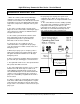
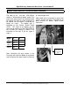
Flame icon indicates
burner is ignited and
that flame has been
sensed.
Check mark in the box
indicates the blow er
proving sw itch contacts
are made
Blower icon
indicates power
to the blower