
Service manual


High-Efficiency Commercial Gas Series - Service Manual
Technical Literature Department 23 Ashland City, Tennessee © 2008
Servicing should only be performed by a Qualified Service Agent
CONTROLS – PRESSURE SWITCHES
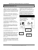
All models are provided with four pressure
switches. These switches are essential to the
safe and proper operation of the unit. The
switches are wired to the central control board
(CCB) individually and each is monitored
individually. The (CCB) is set up to shut the unit
down whenever there is a failure of any of the
switches and declare a fault for each individual
switch. It is important to understand the purpose
of each switch.
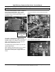
BLOWER PROVER SWITCH
The Blower Prover Switch is used to verify the
combustion blower is operating. This switch has
normally open contacts that close on a pressure
rise. This switch is connected to the burner tap by a
piece of Tygon (soft plastic) tubing. This tubing
must be connected in order for the switch to close
the electrical contacts. The control system requires
that the electrical contacts on this switch be open
before it will energize the blower. After the blower
has been energized the control system requires that
the contacts close. The control system will lock out
and display a fault message on the UIM if either
requirement is not met.
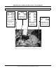
BLOCKED EXHAUST SWITCH
The Blocked Exhaust Switch is used to verify the
water heater's vent (exhaust) piping is not
restricted. This switch has normally closed
contacts that open on a pressure rise. This
switch is connected to the exhaust elbow with
sections of aluminum and Tygon (soft plastic)
tubing. The control system requires that the
electrical contacts on this switch be closed at all
times. The control system will lock out and display a
fault message on the UIM if this requirement is not
met. If the “Blocked Exhaust” fault message is
displayed on the UIM ensure the condensate hose
connected to the exhaust elbow is draining
properly. Check for obstructions in the exhaust vent
piping. Ensure the equivalent feet of vent pipe for
the specific model has not been exceeded. Check
the vent length tables on page 9
BLOCKED INTAKE AIR SWITCH
The Blocked Intake Air Switch is used to verify the
water heater's supply of combustion air (intake) is
not restricted. This switch has normally closed
contacts that open on a pressure fall. This switch
is connected to the pressure tap on the blower's
intake air PVC flange with Tygon (soft plastic)
tubing. The control system requires that the
electrical contacts on this switch be closed at all
times. The control system will lock out and display a
fault message on the UIM if this requirement is not
met. If the “Blocked Inlet” fault message is
displayed on the UIM ensure the intake air piping
on direct vent installations is not restricted. Ensure
the screen on the intake air connection to the water
heater was removed on direct vent installations.
Ensure the screen on the intake air connection to
the water heater is free of debris on conventional
vent installations. Ensure the equivalent feet of
intake air pipe for the specific model has not been
exceeded. Check the vent length tables on page 9
LOW GAS PRESSURE SWITCH
The Low Gas Pressure Switch is used to verify the
supply gas pressure is at or above minimum
requirements. This switch has
normally open
contacts that close on a pressure rise. The
control system requires that the electrical contacts
on this switch be closed at all times. The control
system will lock out and display a fault message on
the UIM if this requirement is not met.
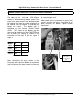
Low Gas Pressure
Sw itch
Pressure
Sw itches