Tankless Water Heater System Design Manual Plumbing schematics for single and multiple tankless water heaters in use with domestic systems, recirculation, and storage tanks.
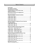
Table of Contents Certifications..................................................................................3 Water Quality and Scale ................................................................4 Pump Sizing for Circulation..........................................................5 Tank Water Heaters in a Circulation Loop...................................6 Additional Guidelines ....................................................................6 Pump Sizing for Storage Tank Applications ........
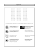
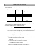
Approvals ATI-305-N ATI-305-P ATO-305-N ATO-305-P ATI-505-N ATI-505-P ATO-505-N ATO-505-P ATI-705-N ATI-705-P ATO-705-N ATO-705-P ATI-705A-N ATI-705A-P ATO-705A-N ATO-705A-P GTS-305-NI GTS-305-PI GTS-305-NE GTS-305-PE GTS-505-NI GTS-505-PI GTS-505-NE GTS-505-PE GTS-705-NI GTS-705-PI GTS-705-NE GTS-705-PE GTS-705-NIA GTS-705-PIA GTS-705-NEA GTS-705-PEA GT-305-NI GT-305-PI GT-305-NE GT-305-PE GT-505-NI GT-505-PI GT-505-NE GT-505-PE GT-705-NI GT-705-PI GT-705-NE GT-705-PE AGT-705-NI AGT-705-PI AGT-705-NE AG
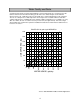
Water Quality and Scale A complete water analysis and an understanding of system requirements are needed to protect the tankless water heaters and water heating systems from scale. Water analysis shows whether water is hard or soft. Hard water, unless treated, will cause scaling or liming of the heat exchanger. The rate of scaling increases with temperature and usage because calcium carbonate and other scaling compounds lose solubility (fall out of solution) at higher temperatures.
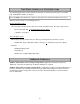
Pump Sizing for Circulation 1. Use the chart below or one appropriate for your conditions to determine the heat loss in the length of the hot water supply and return piping. For example, 100 ft of 1-1/2 in bare copper tubing results in a heat loss of 5300 Btu/h. Approximate Heat Loss from Piping at 140 ºF Inlet, 70 ºF Ambient * Nominal Size, in. Bare Copper Tubing, Btu/h-ft 1/2 in. Glass Fiber Insulated Copper Tubing, Btu/h-ft 3/4 30 17.7 1 38 20.3 1-1/4 45 23.4 1-1/2 53 25.4 2 66 29.
Tank Water Heaters in a Circulation Loop The following applies when using a tank water heater (gas or electric) to provide heat for a circulation loop. Drawing WH-1-RGE is an example. The heat output of the tank must be equal to or greater than the calculated circulation loop heat loss. (Reference page 6, Step 1 on calculating heat loss).
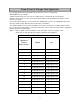
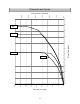
Pump Sizing for Storage Tank Application The following applies when using tankless water heaters to recover a storage tank. Drawing WH-1-B is an example. Tankless water heaters have a pressure loss which must be considered in the system design. Reference the pressure loss curve for the heater model being used to determine the pump size for the desired recovery rate. For recommended pump sizes use the table below.
Pressure Loss (psi) 8 0.0 5.0 10.0 15.0 20.0 25.0 30.0 35.0 40.0 45.0 0 1 2 3 4 305i 305e 6 Water Flow (gpm) 5 7 8 9 10 11 0.0 10.0 20.0 30.0 40.0 50.0 60.
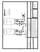
June 11, 2007 Drawing Date: WH-1 Drawing Number: 3/4 " C old W ater S upply Line G as S upply Tankless Water Heaters This is not an engineering drawing; it is intended only as a guide and not as a replacement for professional engineering project drawings. This drawing is not intended to describe a complete system. It is up to the contractor or engineer to determine the necessary components and configuration of the particular system to be installed.
February 27, 2008 Drawing Date: WH-2 Drawing Number: Sub 1 Primary This is not an engineering drawing; it is intended only as a guide and not as a replacement for professional engineering project drawings. This drawing is not intended to describe a complete system. It is up to the contractor or engineer to determine the necessary components and configuration of the particular system to be installed. The drawing does not imply compliance with local building code requirements.
February 27, 2008 Drawing Date: WH-3 Drawing Number: This is not an engineering drawing; it is intended only as a guide and not as a replacement for professional engineering project drawings. This drawing is not intended to describe a complete system. It is up to the contractor or engineer to determine the necessary components and configuration of the particular system to be installed. The drawing does not imply compliance with local building code requirements.
February 27, 2008 Drawing Date: WH-4 Drawing Number: Sub 2 Tankless Water Heater This is not an engineering drawing; it is intended only as a guide and not as a replacement for professional engineering project drawings. This drawing is not intended to describe a complete system. It is up to the contractor or engineer to determine the necessary components and configuration of the particular system to be installed. The drawing does not imply compliance with local building code requirements.
February 27, 2008 Drawing Date: WH-5 Drawing Number: Sub 3 Tankless Water Heater Domestic Hot Water - Standard Installation 5 Tankless Water Heaters Preferred Piping Installation Sub 2 Tankless Water Heater This is not an engineering drawing; it is intended only as a guide and not as a replacement for professional engineering project drawings. This drawing is not intended to describe a complete system.
February 27, 2008 Drawing Date: WH-6 Drawing Number: S Solenoid Valve Boiler Drain Valve Check Valve Pressure Relief Valve Circulating Pump 3/4" Union Key Cold Water Supply Line Gas Supply * Refer to Tankless Accessories and Model Applicability for electronic connection details.
June 11, 2007 Drawing Date: WH-1-D Drawing Number: 1/4" Minimum Normally Open Solenoid Valve Minimum 3/4" Hot Water Supply Line S Route drain per local codes 3/4" Minimum Normally Closed Solenoid Valve Outdoor Tankless Water Heater Vacuum Breaker Outdoor Tankless Water Heater Tankless Equipment List 1 QTY Solenoid Valve Boiler Drain Valve Check Valve S Circulating Pump 3/4" Union Pressure Relief Valve Pressure Regulator Key 3/4" Ball Valve Minimum 3/4 " C old W ater S upply Line Ga
February 27, 2008 Drawing Date: Route drain per local codes 1/4" Normally Open Solenoid Valve Primary Outdoor Tankless Water Heater This is not an engineering drawing; it is intended only as a guide and not as a replacement for professional engineering project drawings. This drawing is not intended to describe a complete system. It is up to the contractor or engineer to determine the necessary components and configuration of the particular system to be installed.
Hot Water Supply Line Vacuum Breaker February 27, 2008 Drawing Date: WH-3-D Drawing Number: heater, and the drain down solenoid valve opens, allowing the water heater and associated piping to drain. Ensure that you run the drain for the solenoids per local codes.
The vacuum breaker line should be located inside the building structure. line should be located inside the building structure. outside building structure. These are indicated by being above the dashed line.
February 27, 2008 Drawing Date: WH-1-RGE Drawing Number: Important: Install return line to the hot supply line as close as possible to the Tankless water heater Tankless Water Heater Gas or Electric Tank Water Heater Expansion Tank 1 QTY This is not an engineering drawing; it is intended only as a guide and not as a replacement for professional engineering project drawings. This drawing is not intended to describe a complete system.
June 11, 2007 Drawing Date: WH-1-R Drawing Number: Minimum 3/4 “ Hot Water Supply Line (To eliminate cold water sandwich e ect caused by fre quent On/O operation) (Optional) 2-6 Gallon Storage Tank Tankless Water Heater Tankless Water Heater Tankless Equipment List Aquastat Connection This is not an engineering drawing; it is intended only as a guide and not as a replacement for professional engineering project drawings. This drawing is not intended to describe a complete system.
February 27, 2008 Drawing Date: WH-2-RGE Drawing Number: Gas or Electric Tank Water Heater Expansion Tank Sub 1 Primary Important: Install return line to the hot supply line as close as possible to the Rinnai water heater Tankless Water Heater Tankless Water Heater Building Supply Minimum 3/4 “ Cold Water Supply Line Gas Supply Line This is not an engineering drawing; it is intended only as a guide and not as a replacement for professional engineering project drawings.
February 27, 2008 Drawing Date: WH-2-R Drawing Number: Domestic Hot Water - Circulation Systems 2 Tankless Water Heaters Optional Piping Installation Building Outlets (To eliminate cold water sandwich e ect caused by fre quent On/O operation) Aquastat Connection Sub 1 Primary (Optional) 2-10 Gallon Storage Tank Tankless Water Heater Tankless Water Heater This is not an engineering drawing; it is intended only as a guide and not as a replacement for professional engineering project drawings.
February 27, 2008 Drawing Date: WH-3-RGE Drawing Number: Tankless Water Heater Sub 1 Tankless Water Heater Primary This is not an engineering drawing; it is intended only as a guide and not as a replacement for professional engineering project drawings. This drawing is not intended to describe a complete system. It is up to the contractor or engineer to determine the necessary components and configuration of the particular system to be installed.
February 27, 2008 Drawing Date: WH-6-RGE Drawing Number: Hot Water Supply Line Pump should be controlled by an Aquastat, Timer or Combination Aquastat and Timer. Pump to be sized to maintain circulation loop temperature. The pump should be sized to overcome the pressure loss through the tank water heater, and supply and return plumbing in the circulation loop. Reference the section Pump Sizing for Circulation. Pump to be of bronze or stainless construction.
February 27, 2008 Drawing Date: WH-1-B Drawing Number: Pump / Aquastat Control Wire This is not an engineering drawing; it is intended only as a guide and not as a replacement for professional engineering project drawings. This drawing is not intended to describe a complete system. It is up to the contractor or engineer to determine the necessary components and configuration of the particular system to be installed. The drawing does not imply compliance with local building code requirements.
February 27, 2008 Drawing Date: WH-1-B-R Drawing Number: Building Hot Water Return Line Pump / Aquastat Control Wire Gas Supply Set @ 20°F above storage tank Aquastat Expansion Tank This is not an engineering drawing; it is intended only as a guide and not as a replacement for professional engineering project drawings. This drawing is not intended to describe a complete system.
February 27, 2008 Drawing Date: WH-2-B Drawing Number: Submersible Aquastat (set @ 20°F below Tankless Temperature Setting) (No Burner or Heating Element) Storage Tank Building Hot Water Supply Line Set water heaters @ 20°F above storage tank Aquastat Pump / Aquastat Control Wire Tankless Water Heater This is not an engineering drawing; it is intended only as a guide and not as a replacement for professional engineering project drawings.
February 27, 2008 Drawing Date: WH-2-B-R Drawing Number: Set water heaters @ 20°F above storage tank Aquastat Pump / Aquastat Control Wire Tankless Water Heater Domestic Hot Water - Backup Storage / Circulation 2 Tankless Water Heaters Preferred Piping Installation Building Hot Water Return Line Tankless Water Heater This is not an engineering drawing; it is intended only as a guide and not as a replacement for professional engineering project drawings.
February 27, 2008 Drawing Date: WH-3-B Drawing Number: Submersible Aquastat (set @ 20°F below Tankless Temperature Setting) (No Burner or Heating Element) Storage Tank Building Hot Water Supply Line Pump / Aquastat Control Wire Tankless Water Heater Tankless Water Heater This is not an engineering drawing; it is intended only as a guide and not as a replacement for professional engineering project drawings. This drawing is not intended to describe a complete system.
February 27, 2008 Drawing Date: WH-3-B-R Drawing Number: Building Circulation Pump Tankless Water Heater Pump / Aquastat Control Wire Tankless Water Heater Domestic Hot Water - Backup Storage / Circulation 3 Tankless Water Heaters Preferred Piping Installation Building Hot Water Return Line Tankless Water Heater Gas Supply Tankless Commercial Water Heaters Solenoid Valve Boiler Drain Valve Check Valve S Circulating Pump 3/4" Union Pressure Relief Valve Pressure Regulator Key 3/4" Ball
Tankless Water Heater February 27, 2008 Drawing Date: WH-6-B Drawing Number: Submersible Aquastat (set @ 20°F below Tankless Temperature Setting) (No Burner or Heating Element) Storage Tank Building Hot Water Supply Line Pump / Aquastat Control Wire Tankless Water Heater This is not an engineering drawing; it is intended only as a guide and not as a replacement for professional engineering project drawings. This drawing is not intended to describe a complete system.
February 27, 2008 Drawing Date: WH-6-B-R Drawing Number: Building Circulation Pump Submersible Aquastat (set @ 20°F below Tankless Temperature Setting) (No Burner or Heating Element) Storage Tank Expansion Tank Building Hot Water Supply Line Tankless Water Heater Tankless Water Heater Pump / Aquastat Control Wire Tankless Water Heater Tankless Water Heater This is not an engineering drawing; it is intended only as a guide and not as a replacement for professional engineering project drawin
June 11, 2007 Drawing Date: M-1-F Drawing Number: Circulating Pump H2 V3 Hot Wa ter Line Maintenance - Scale Flush Procedure 1 Tankless Water Heater H3 V1 This is not an engineering drawing; it is intended only as a guide and not as a replacement for professional engineering project drawings. This drawing is not intended to describe a complete system. It is up to the contractor or engineer to determine the necessary components and configuration of the particular system to be installed.
Notes 34
Notes 35
• 500 Tennessee Waltz Parkway • Ashland, TN 37015 •