
Instruction manual

34 www. americanwaterheater .com 328767-001
Vent Pipe Installation
The following guidelines should be followed when installing
the air intake and exhaust vent system:
• Venting should be as direct as possible with a minimum
number of pipe fi ttings.
• Vent diameter must not be reduced unless specifi cally
noted in the installation instructions.
• Support all horizontal pipe runs every 4’ and all vertical
pipe runs every 5’ or according to local codes or venting
manufacturer’s instructions.
• Vents run through unconditioned spaces where
below freezing temperatures are expected, are not
recommended.
• Vents run through unconditioned spaces inside a
building may result in the condensation of fl ue gases
during the winter season. The rubber coupling joined to
the blower includes a nipple with a cap. In installations
such as this connect a condensation trap to this nipple.
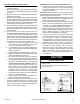
The combustion air intake and exhaust vent system and
termination may be installed in one of the following type
terminations:
1. Horizontal (2 Pipe) (air intake and exhaust vent)
2. Vertical (2 Pipe) (air intake and exhaust vent)
3. Concentric Vent Termination (horizontal/side wall
installation).
4. Concentric Vent Termination (vertical/roof installation).
All pipe, fi ttings, pipe cement, primers and procedures
must conform to American National Standard Institute and
American Society for Testing and Materials (ANSI/ASTM)
standards. This water heater has been design certifi ed by
CSA International for use with the specifi ed (CSA) listed
plastic vent pipe.
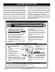
• Primers and cements are
extremely flammable, and must
not be stored or used near heat
or open flame.
• Also, use only in a well venti-
lated area.
Fire Hazard
WARNING
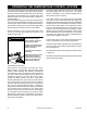
• Cans of cement and primer should
be closed at all times when not in
use to prevent evaporation of
chemicals and hardening of cement.
• They are also very flammable and
should be kept away from heat or
flame.
Fire Hazard
WARNING
Do not use solvent cement to connect the exhaust vent
system to the blower. Use the rubber coupling and gear
clamps instead. This connection must be removable to
service the heater. All other joints in the air intake and
exhaust vent systems must be properly cemented.
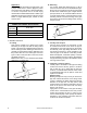
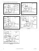
Vent Pipe Runs
1. The exhaust vent system must not, under any
circumstances, be run downhill then run uphill thus
forming a valley. It may leave a space to accumulate
condensation and block vent pipe.
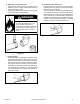
2. Horizontal runs require a minimum 1/8” rise per
5’ and a support every 4’ or according to venting
manufacturer’s instructions. Ensure there is enough
height between heater and termination to raise vent
pipe runs the required distance.
3. Vertical runs require a support every 5’ that must
provide proper support to prevent stress on the pipes
or according to venting manufacturer’s instructions.
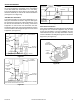
Vent Terminal Installations
Important: The vent system must terminate so that proper
clearances are maintained as cited in local codes or the
latest edition of “National Fuel Gas Code”, ANSI Z223.1/
NFPA 54.
In addition, the manufacturer recommends the vent
terminal not to be installed closer than 6” from an inside
or outside corner.
Plan the vent system layout so that proper clearances
are maintained from plumbing and wiring. Vent pipes
serving power vented appliances are classifi ed by building
codes as “vent connectors”. Required clearances from
combustible materials must be provided in accordance
with information in this manual under ““Locating The New
Water Heater” and with the latest edition of “National
Fuel Gas Code”, ANSI Z223.1/NFPA 54 and local codes.