Instruction Manual RESIDENTIAL GAS WATER HEATERS NOT FOR USE IN MANUFACTURED (MOBILE) HOMES Low Lead Content • For Your Safety • AN ODORANT IS ADDED TO THE GAS USED BY THIS WATER HEATER. ALL TECHNICAL AND WARRANTY QUESTIONS: SHOULD BE DIRECTED TO THE LOCAL DEALER FROM WHOM THE WATER HEATER WAS PURCHASED. IF YOU ARE UNSUCCESSFUL, PLEASE WRITE TO THE COMPANY LISTED ON THE RATING PLATE ON THE WATER HEATER.
SAFE INSTALLATION, USE AND SERVICE Your safety and the safety of others is extremely important in the installation, use and servicing of this water heater. Many safety-related messages and instructions have been provided in this manual and on your own water heater to warn you and others of a potential injury hazard. Read and obey all safety messages and instructions throughout this manual.
GENERAL SAFETY 3
TABLE OF CONTENTS SAFE INSTALLATION, USE AND SERVICE............................2 GENERAL SAFETY..................................................................3 TABLE OF CONTENTS.............................................................4 INTRODUCTION.......................................................................4 Preparing for the New Installation......................................4 TYPICAL INSTALLATION.......................................................5,6 LOCATING THE NEW WATER HEATER.
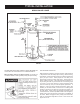
TYPICAL INSTALLATION GET TO KNOW YOUR WATER HEATER - GAS MODELS A Vent Pipe B Drafthood C Anode D Hot Water Outlet E Outlet F Insulation G Gas Supply H Manual Gas Shut-off Valve I Ground Joint Union J Sediment Trap K Inner Door L Outer door M Union N Inlet Water Shut-off Valve O Cold Water Inlet P Inlet Dip Tube Q Temperature-Pressure Relief Valve R Rating Plate S Flue Baffle(s) T Gas Control Valve/Thermostat U Drain Valve V Pilot and Main Burner W Flue X Metal Drain Pan (T) GAS CON
TYPICAL INSTALLATION MIXING VALVE USAGE FIGURE 2. This water heater has been design certified as complying with ANSI Z21.10.3 current edition for water heaters and is considered suitable for: HOTTER WATER CAN SCALD: Water heaters are intended to produce hot water. Water heated to a temperature which will satisfy space heating, clothes washing, dish washing, and other sanitizing needs can scald and permanently injure you upon contact.
LOCATING THE NEW WATER HEATER Facts to Consider About the Location Carefully choose an indoor location for the new water heater, because the placement is a very important consideration for the safety of the occupants in the building and for the most economical use of the water heater. This water heater is not for use in manufactured (mobile) homes or outdoor installation. Whether replacing an old water heater or putting the water heater in a new location, the following critical points must be observed: 1.
INSULATION BLANKETS Minimum clearances between the water heater and combustible materials are 0 inch at the sides and rear, 4” (102 mm) at the front, and 6” (153 mm) from the vent pipe. Clearance from the top of the jacket is 12” (305 mm) on most models. Note that a lesser dimension may be allowed on some models, refer to the label attached adjacent to the gas control valve on the water heater, see Figure 3. FIGURE 3.
A. ALL AIR FROM INSIDE BUILDINGS: (See Figures 4 and 5) The confined space shall be provided with two permanent openings communicating directly with an additional room(s) of sufficient volume so that the combined volume of all spaces meets the criteria for an unconfined space. The total input of all gas utilization equipment installed in the combined space shall be considered in making this determination.
INSTALLING THE NEW WATER HEATER Water Piping Closed Water Systems Water supply systems may, because of code requirements or such conditions as high line pressure, among others, have installed devices such as pressure reducing valves, check valves, and back flow preventers. Devices such as these cause the water system to be a closed system. Thermal Expansion HOTTER WATER CAN SCALD: Water heaters are intended to produce hot water.
The valve must be marked with a maximum set pressure not to exceed the marked maximum working pressure of the water heater (150 psi = 1,035 kPa) and a discharge capacity not less than the water heater input rate as shown on the model rating plate. For safe operation of the water heater, the relief valve must not be removed from its designated opening nor plugged. The temperature-pressure relief valve must be installed directly into the fitting of the water heater designed for the relief valve.
VENT DAMPERS - Any vent damper, whether it is operated thermally or otherwise must be removed if its use inhibits proper drafting of the water heater. Thermally Operated Vent Dampers: this gas-fired water heater has a thermal efficiency at or above 80% which may produce a relatively low flue gas temperature. Such temperatures may not be high enough to properly open thermally operated vent dampers. This would cause spillage of the flue gases and may cause carbon monoxide poisoning.
Make sure the gas supplied is the same type listed on the model rating plate. The inlet gas pressure must not exceed 14 inch water column (2.6 kPa) for natural and propane (L.P.) gas. The minimum inlet gas pressure shown on the rating plate is that which will permit firing at rated input. If the gas control valve is subjected to pressures exceeding 1/2 pound per square inch (3.5 kPa), the damage to the gas control valve could result in a fire or explosion from leaking gas. FIGURE 12.
FIGURE 14. GAS PIPING WITH ALL BLACK IRON PIPE TO GAS CONTROL. Use pipe joint compound or teflon tape marked as being resistant to the action of petroleum [Propane (L.P.)] gases. SEDIMENT TRAPS A sediment trap shall be installed as close to the inlet of the water heater as practical at the time of water heater installation. The sediment trap shall be either a tee fitting with a capped nipple in the bottom outlet or other device recognized as an effective sediment trap.
FOR YOUR SAFETY READ BEFORE LIGHTING WARNING: If you do not follow these instructions exactly, a fire or explosion may result causing property damage, personal injury or loss of life. BEFORE LIGHTING: ENTIRE SYSTEM MUST BE FILLED WITH WATER AND AIR PURGED AT FAUCETS. A. B. This appliance has a pilot which must be lighted by hand. When lighting the pilot, follow these instructions exactly. BEFORE LIGHTING: smell all around the appliance area for gas.
TEMPERATURE REGULATION Never allow small children to use a hot water tap, or to draw their own bath water. Never leave a child or handicapped person unattended in a bathtub or shower. Short repeated heating cycles caused by small hot water uses can cause temperatures at the point of use to exceed the thermostat setting by up to 30°F (16.7°C). If you experience this type of use you should consider using lower temperature settings to reduce scald hazards.
conditions will cause a reaction between this rod and the water. The most common complaint associated with the anode rod is one of a “rotten egg smell” in the hot water. This odor is derived from hydrogen sulfide gas dissolved in the water. The smell is the result of four factors which must all be present for the odor to develop: Because of the suddenness and amount of water, condensation water may be diagnosed as a “tank leak”.
PERIODIC MAINTENANCE Venting System Inspection You should check for sooting. Soot is not normal and will impair proper combustion. Soot build-up indicates a problem that requires correction before further use. Turn “OFF” gas to water heater and leave off until repairs are made, because failure to correct the cause of the sooting can result in a fire causing death, serious injury, or property damage. NATURAL PROPANE At least once a year a visual inspection should be made of the venting system.
INSTALLED IN SUITABLE AREA: To insure sufficient ventilation and combustion air supply, proper clearances from the water heater must be maintained. See “Locating the New Water Heater” section. Combustible materials such as clothing, cleaning materials, or flammable liquids, etc. must not be placed against or adjacent to the water heater which can cause a fire. In replacing the anode: 1. Turn off gas supply to the water heater. 2.
Draining AND FLUSHING 3. Turning counterclockwise ( screw handle. ), remove the hex cap below the 4. Remove the was her and put the new one in place. 5. Screw the handle and cap assembly back into the drain valve and retighten using a wrench. DO NOT OVER TIGHTEN. 6. Follow instructions in the “Filling The Water Heater” section. 7. Check for leaks. 8. Follow the lighting Instructions in the “Lighting and Operating Instructions” section to restart the water heater.
LEAKAGE CHECKPOINTS Read this manual first. Then before checking the water heater make sure the gas supply has been turned “OFF”, and never turn the gas “ON” before the tank is completely full of water. Never use this water heater unless it is completely filled with water. To prevent damage to the tank, the tank must be filled with water. Water must flow from the hot water faucet before turning “ON” gas to the water heater. A.
REPAIR PARTS Key No.
TROUBLESHOOTING GUIDELINES These guidelines should be utilized by a qualified service technician. Problem WATER LEAKS LEAKING T&P VALVE SMELLY WATER PILOT WILL NOT LIGHT BURNER WILL NOT STAY LIT PILOT OUTAGE NOT ENOUGH HOT WATER WATER TOO HOT WATER HEATER SOUNDS SIZZLING OR RUMBLING SOOTING Cause Solution Improperly sealed, hot or cold supply connection, relief valve, drain valve, or thermostat threads. Tighten threaded connections. Leakage from other appliances or water lines.
NOTES 25
NOTES 26
NOTES 27