Installation and Operating Manual RESIDENTIAL GAS WATER HEATERS DIRECT VENTED GAS MODELS NOT FOR USE IN MANUFACTURED (MOBILE) HOMES www.americanwaterheater.com • For Your Safety • AN ODORANT IS ADDED TO THE GAS USED BY THIS WATER HEATER. ALL TECHNICAL AND WARRANTY QUESTIONS: SHOULD BE DIRECTED TO THE LOCAL DEALER FROM WHOM THE WATER HEATER WAS PURCHASED. IF YOU ARE UNSUCCESSFUL, PLEASE CONTACT THE COMPANY LISTED ON THE RATING PLATE ON THE WATER HEATER.
TABLE OF CONTENTS SAFE INSTALLATION, USE AND SERVICE . . . . . . . . . . . 3 GENERAL SAFETY . . . . . . . . . . . . . . . . . . . . . . . . . . . . . . 4 INTRODUCTION . . . . . . . . . . . . . . . . . . . . . . . . . . . . . . . . 6 Qualified Installer Or Service Agency . . . . . . . . . . . . 6 Preparing For The Installation . . . . . . . . . . . . . . . . . . 6 LIGHTING INSTRUCTIONS. . . . . . . . . . . . . . . . . . . . . . . 28 TEMPERATURE REGULATION . . . . . . . . . . . . . . . . . . .
SAFE INSTALLATION, USE AND SERVICE Your safety and the safety of others is extremely important in the installation, use and servicing of this water heater. Many safety-related messages and instructions have been provided in this manual and on your own water heater to warn you and others of a potential injury hazard. Read and obey all safety messages and instructions throughout this manual.
GENERAL SAFETY WARNING Fire or Explosion Hazard • Do not store or use gasoline or other flammable vapors and liquids in the vicinity of this water heater, the vent termination hood or any other appliance. • Avoid all ignition sources if you smell gas. • Do not expose water heater control to excessive gas pressure. • Use only gas shown on rating plate. • Maintain required clearances to combustibles. • Keep ignition sources away from faucets after extended period of non-use.
GENERAL SAFETY DANGER FLAMMBLE Vapors from flammable liquids may explode and catch fire causing death or severe burns. WARNING Breathing Hazard - Carbon Monoxide Gas • Install vent system in accordance with codes. • Do not operate water heater if flood damaged. • For operation above 7,700’, a high altitude orifice must be installed. • Do not operate if soot buildup is present.
INTRODUCTION Thank You for purchasing this water heater. Properly installed and maintained, it should give you years of trouble free service. This water heater is suitable for potable water heating and space heating applications but not for space heating only applications.
INSTALLATION REQUIREMENTS FOR THE COMMONWEALTH OF MASSACHUSETTS COMMONWEALTH OF MASSACHUSETTS For all side wall terminated, horizontally vented power vent, direct vent and power direct vent gas fueled water heaters installed in every dwelling, building or structure used in whole or in part for residential purposes, including those owned or operated by the Commonwealth and where the side wall exhaust vent termination is less than seven (7) feet above finished grade in the area of the venting, including but n
INSTALLATION GRAPHIC: GAS-FIRED POTABLE WATER HEATING/SPACE HEATING SYSTEM • If your water heater will be installed in the Commonwealth of Massachusetts, refer to the following graphic during installation and during modifications to the water supply system. TYPICAL MIXING VALVE INSTALLATION COMBINATION SPACE HEATING / POTABLE WATER HEATING SYSTEM EXPANSION TANK TEMPERED WATER TO FIXTURES (MUST MEET TEMPS LISTED IN MASS.
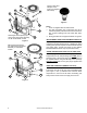
TYPICAL INSTALLATION GET TO KNOW YOUR WATER HEATER - GAS MODELS (LIST REFERENCING FIGURES 1-5) 1 2 3 4 5 6 7 8 9 10 11 12 13 14 15 Vent Termination Hood Wall Plate ***Vent Pipe Cold Water Inlet Nipple/Diptube **Combo Heating System Supply Outlet (Optional) T&P Valve Gas Control Valve/Thermostat (Honeywell) **Combo Heating System Return Inlet (Optional) *Discharge Pipe Drain Valve Outer Gas Door Manifold Door Assembly (behind outer door) (see Figure 3 & Figure 4) *Floor Drain *Metal Drain Pan Flexible Manif
30 39 37 40 31 38 Vacuum relief valve install per local codes (not supplied with heater). 36 Figure 5 32 35 33 Natural gas and Propane (LP) main burner with igniter assembly for 38k to 42k Btu/hr models 34 REPLACEMENT PARTS AND DELIMING PRODUCTS Replacement parts and recommended delimer may be ordered through authorized servicers or distributors. When ordering parts, provide complete model and serial numbers (see rating plate), quantity and name of part desired.
LOCATING THE NEW WATER HEATER FACTS TO CONSIDER ABOUT THE LOCATION Carefully choose an indoor location for the new water heater because the placement is a very important consideration for the safety of the occupants in the building and for the most economical use of the appliance. This water heater is not for use in manufactured (mobile) homes or outdoor installation. Whether replacing an old water heater or putting the water heater in a new location, the following critical points must be observed: 1.
AIR REQUIREMENTS For safe operation an adequate supply of fresh, uncontaminated air must be provided for combustion. This gas-fired water heater is a direct vent model. It connects directly to the outside of the building through the vent termination hood. The hood operates as both the combustion air intake and the heater exhaust port (see Figure 16). All combustion air is obtained from outside the building through this hood.
WARNING FLAMMABLES Flammable Vapors FIRE AND EXPLOSION HAZARD Can result in serious injury or death Do not store or use gasoline or other flammable vapors and liquids in the vicinity of this or any other appliance. Storage or use of gasoline or other flammable vapors or liquids in the vicinity of this or any other appliance can result in serious injury or death.
WATER PIPING Water Pressure The water supply pressure should not exceed 80 psi. If this occurs, a pressure reducing valve with a bypass should be installed in the cold water inlet line. This should be placed on the supply to the entire house in order to maintain equal hot and cold water pressures. See also “Closed Water Systems” and “Thermal Expansion” sections. DANGER Children, the elderly and the disabled and are at highest risk of scald injury. Feel water before bathing or showering.
INSTALLING THE NEW WATER HEATER WATER PIPING INSTALLATION Note: Water piping and vent piping occupy the space above the water heater. Plan the water piping to ensure it does not cause interference with the vent piping (see “Venting”). • The system should be installed only with piping that is suitable for potable (drinkable) water such as copper, CPVC, or polybutylene. This water heater must not be installed using iron piping or PVC water piping.
A properly-sized and charged thermal expansion tank must be installed on all closed systems to control the harmful effects of thermal expansion. Contact a plumbing service agency or your retail supplier regarding the installation of a thermal expansion tank. Note: To protect against untimely corrosion of hot and cold water fittings, it is recommended that di-electric unions or couplings be installed on this water heater when connected to copper pipe.
The T&P valve must be manually operated at least once a year. Caution should be taken to ensure 1. no one is in front of or around the outlet of the discharge line, and 2. the water manually discharged will not cause any bodily injury or property damage because the water may be extremely hot.
SPACE HEATING AND POTABLE WATER SYSTEMS This appliance has been design certified as complying with American National Standard/CSA Standard for water heaters and are considered suitable for Water (Potable) Heating and Space Heating. Note: This water heater may be used in combination potable water/space heating system. Do not use in a space heating only application. WARNING Toxic Chemical Hazard • Do not connect to non-potable water system.
COMBO HEATING This section serves as a guide for the installation and use of “Combo” heating systems utilizing a domestic water heater that has been specifically approved for such use. It is written for those knowledgeable in the required trades and professionals involved in the design and installation of Combo Heating Systems. It is the responsibility of the installer/designer to follow all applicable codes to ensure the effectiveness and safety of the installation.
There must be: GAS PIPING • A readily accessible manual shut-off valve in the gas supply line serving the water heater, and WARNING • A sediment trap ahead of gas control valve/thermostat Fire and Explosion Hazard • Do not use water heater with any gas other than the gas shown on the rating plate. • Excessive pressure to gas control valve can cause serious injury or death. • Turn off gas lines during installation. • Contact qualified installer or service agency.
CERTIFIED GAS SUPPLY FLEX PIPE (PROPERLY SIZED FOR THE HEATER INPUT RATE) GROUND JOINT UNION (OPTIONAL) SEDIMENT TRAP 3” MIN. GAS CONTROL VALVE CAP HIGH ALTITUDE INSTALLATIONS Installations above 7,700’. require replacement of the burner orifice in accordance with the current edition of the “National Fuel Gas Code” (ANSI Z223.1/NFPA 54).
VENTING This direct vent water heater uses a sealed venting system to supply fresh combustion air to the heater and to exhaust the products of combustion (flue gases) to the outdoors. The venting is a “pipe in a pipe” system. The inner (3”) piping carries out the exhaust flue gases while the outer (6”) piping carries in fresh combustion air.
HOT EXHAUST GAS OUT FRESH COMBUSTION AIR IN Figure 18 VENT CONNECTIONS After the location for the vent terminal has been selected as outlined in Figure 6 & Figure 15, use the following illustrations for installation: SCREW Figure 16 Be sure venting is properly connected to prevent escape of dangerous flue gases which could cause deadly asphyxiation. DV TERMINATION SAFETY COVER When the heater is in operation the vent termination hood will be hot (see Figure 16).
VENT ASSEMBLY The vent piping and the vent termination hood are to be connected as shown in Figure 20. Maintain vent clearances to combustibles as shown in Figure 21. Depending on your access to where the vent termination passes through the wall, you may wish to connect the piping and vent termination hood together first. Inside the vent piping there are springs that hold the two corrugated pipes in position. When the pipes are stretched to the required length, the springs will remain properly spaced.
SMOOTH, EASY CURVE OUTER CORRUGATED PIPE INNER CORRUGATED PIPE RESTRICTER PLATE APPLY SILICONE TO AIRBOX BEFORE ATTACHING PIPING FLUE TUBE REDUCER APPLY SILICONE GEAR CLAMP SECURE WITH A SHEET METAL SCREW Figure 23 Figure 25 VENT CONNECTION TO THE WATER HEATER Bend both the corrugated pipes toward the flue connection on the water heater. Pull and connect the inner corrugated pipe to the water heater’s flue tube reducer with hi-temp red silicone (included) and gear clamp.
Low Vent installation High Vent installation 1 5 9 6 1 A B 8 7 C 12” MIN. BELOW SOFFIT 1 5 ABOVE ANTICIPATED SNOW LEVEL OR 12” ABOVE GRADE 17” MIN. 1 6 72” MAX. Figure 28 2 DIM. 4038 5040 A 80” MAX. B 9” MIN. 5047 C (RECOMMENDED) 63.63” 73.00” 74.00” C (MINIMUM) 60.75 69.50 70.50 D 14.25” MIN. NOTE: Dimension “C” is the height above to floor to the center of the termination hole through the exterior wall.
INSTALLATION CHECKLIST Note: Use and complete this checklist before lighting the heater. Correct any conditions that do not meet these instructions. Water Heater Location Centrally located with the water piping system. Located as close to gas piping and vent pipe system as possible. Located indoors and in a vertical position. Protected from freezing temperatures. Proper clearances from combustible surfaces maintained and not installed directly on a carpeted floor.
LIGHTING INSTRUCTIONS FOR YOUR SAFETY READ BEFORE LIGHTING WARNING: If you do not follow these instructions exactly, a fire or explosion may result causing property damage, personal injury or loss of life. BEFORE LIGHTING: ENTIRE SYSTEM MUST BE FILLED WITH WATER AND AIR PURGED FROM ALL LINES FLAMMABLE A. This appliance has a pilot which is lit by a piezoelectric spark gas ignition system. Do not open the inner door of the appliance and try to light the pilot by hand. B.
TEMPERATURE REGULATION TEMPERATURE REGULATION Important: Adjusting the thermostat past the 120°F mark on the temperature dial will increase the risk of scald injury. Hot water can produce first degree burns within: Temperature Adjustment Valves for reducing the point-of-use temperature by mixing cold and hot water are available (see Figure 8). Also available are inexpensive devices that attach to faucets to limit hot water temperatures. Contact a licensed plumber or the local plumbing authority.
FOR YOUR INFORMATION EXTERNAL DAMAGE Do not operate the water heater until it has been fully checked out by a qualified technician, if the water heater: • Has been exposed to fire or damage. • Displays evidence of sooting. • Produces steam or unusually hot water. If the water heater has been flooded it must be replaced. Smoke/Odor It is not uncommon to experience a small amount of smoke and odor during the initial start-up.
STRANGE SOUNDS Possible noises due to expansion and contraction of some metal parts during periods of heat-up and cool-down do not necessarily represent harmful or dangerous conditions. “Air” In Hot Water Faucets Condensation causes sizzling and popping within the burner area during heating and cooling periods and should be considered normal. See “Condensate” in this section. Sediment collecting over time in the bottom of the tank can result in “rumbling” or “percolating” sounds.
MAINTENANCE FOR YOUR SAFETY AND SATISFACTORY OPERATION, IT IS RECOMMENDED THAT THIS HEATER BE CHECKED ONCE A YEAR BY A COMPETENT SERVICE PERSON. USERS OF THIS WATER HEATER SHOULD BE AWARE THAT GAS COMPONENTS WEAR OUT OVER A PERIOD OF TIME. THE GAS CARRYING COMPONENTS OF THIS WATER HEATER SHOULD BE INSPECTED FOR PROPER OPERATION PERIODICALLY BY A QUALIFIED SERVICE TECHNICIAN.
BURNER FLAMES Inspect the burner flames through the viewport and compare them to the drawings in Figure 32. A properly operating burner should produce a soft blue flame. Blue tips with yellow inner cones are satisfactory. The tips of the flame may have a slight yellow tint. The flame should not be all yellow or have a sharp blue-orange color. Contaminated air may cause an orange colored flame.
free the manifold tube and pilot tube. 7. Remove the screws (1/4” nut driver) securing the manifold/burner assembly to the combustion chamber (Figure 34). 8. Carefully remove the manifold/burner assembly from the combustion chamber. BE SURE NOT TO DAMAGE ANY INTERNAL PARTS.
8. Using the pilot screw removed earlier, attach the new pilot/thermopile assembly. Reattach the burner to the manifold using the screws removed earlier. 9. Reinstall the manifold component block in the manifold door. Ensure that the pilot tube and wires are positioned as shown in Figure 38.
PIEZOELECTRIC IGNITER SYSTEM The piezoelectric igniter system consists of the igniter button, electrode, and wire. The pilot is ignited by an electric spark generated when the igniter button is pressed (see Figure 39). THERMOPILE PILOT PILOT/ THERMOPILE BRACKET ELECTRODE WIRE TO ELECTRODE IGNITER BUTTON Figure 39 TESTING THE IGNITER SYSTEM Turn “OFF” the gas to the water heater at the manual gas shut-off valve. Watch the electrode tip while activating the igniter.
To Refill The Water Heater Storage Tank 1. Close the water heater drain valve. 2. Remove the drain hose. 3. Open a nearby hot water faucet and leave open to allow air to escape. 4. Open the cold water inlet valve to the water heater. 5. To purge the lines of any excess air, keep the hot water faucet open for 3 minutes after a constant flow of water is obtained. 6. Turn “ON” the gas supply at the manual gas shut-off valve. 7.
Note: This rod may reduce but not eliminate water odor problems. The water supply system may require special filtration equipment from a water conditioning company to successfully eliminate all water odor problems. Artificially softened water is exceedingly corrosive because the process substitutes sodium ions for magnesium and calcium ions. The use of a water softener may decrease the life of the water heater tank.
LEAKAGE CHECKPOINTS SERVICE If a condition persists or you are uncertain about the operation of the water heater contact a service agency. Use this guide to check a “Leaking” water heater (see Figure 44). Many suspected “Leakers” are not leaking tanks. Often the source of the water can be found and corrected. If you are not thoroughly familiar with gas codes, your water heater, and safety practices, contact your gas supplier or qualified installer to check the water heater.
REFERENCE PARTS LISTING Replacement parts may be ordered through your plumber or the local distributor. When ordering replacement parts, always have the following information ready: 1. Model, Serial and Product number 2. Type of gas 3. Item number 4.
30 39 37 36 40 † 38 31 Flare Nut †† 39 38 37 35 Natural gas and Propane (LP) main burner with igniter assembly for 38k to 42k Btu/hr models Natural gas and Propane (LP) main burner with igniter assembly for 47k Btu/hr models 34 40 30 † Flare Nut †† 31 32 32 33 33 36 Figure 47 34 35 Figure 48 Notes: † The orifice on Natural gas models has Right-hand thread, the orifice on Propane (LP) models has Lefthand thread. †† For Natural gas models the Flare Nut has Right-hand thread.
TROUBLESHOOTING GUIDELINES PROBLEM BURNER WILL NOT IGNITE POSSIBLE CAUSE(S) 1. 2. 3. 4. 5. 6. 7. 8. Pilot not lit Thermostat set too low No gas Dirt in the gas lines Pilot line clogged Main burner line clogged Defective thermopile Defective gas control/thermostat PILOT WILL NOT LIGHT OR REMAIN LIT HIGH OPERATION COSTS PILOT FLAME TOO SMALL 42 1. 2. 3. 4. 5. 6. 7. 8. Light pilot Turn temp.
PROBLEM INSUFFICIENT HOT WATER SLOW HOT WATER RECOVERY DRIP FROM RELIEF VALVE POSSIBLE CAUSE(S) CORRECTION 1. Thermostat set too low 2. Sediment or lime in tank 3. Water heater too small 4. Wrong piping connections 5. Leaking faucets 6. Wasted hot water 7. Long runs of exposed piping 8. Hot water piping in outside wall 9. Low gas pressure 10. Leaks or cracks in dip tube 11. Incorrect plumbing/plumbing crossover 1. Turn temperature dial to desired setting 2.
STATUS LIGHT AND DIAGNOSTIC CODE TROUBLESHOOTING CHART LED STATUS PROBLEM CORRECTIVE ACTION 0 FLASHES (LED NOT LIT) Pilot light is not lit or Turn Gas Control Valve/Thermostat knob to thermopile has not yet reached “OFF”. Wait 10 minutes, then attempt to relight normal operating temperature. Pilot by following the lighting instructions on the water heater’s label. Until the thermopile reaches its normal operating temperature, the Status Light will not blink, even if the Pilot is lit.
LED STATUS PROBLEM CORRECTIVE ACTION 4 FLASHES The Gas Control Valve’s temperature sensor has detected that the water temperature was too high. Once this condition occurs, the Main Burner and the Pilot Light will be shut off. Since the Pilot light will be off, should this condition occur, this Flash Code will only be displayed immediately after the Pilot has been relit. Turn Gas Control Valve/Thermostat knob to “OFF”. Relight pilot and verify 4 flashes.
NOTES 46 www.americanwaterheater.
NOTES www.americanwaterheater.
500 Princeton Road, Johnson City, TN 37605 Phone: 800-999-9515 • Fax: 800-999-5210 www.americanwaterheater.