
Instruction manual


www. americanwaterheater .com 19
COMBO HEATING
This section serves as a guide for the installation and use
of “Combo” heating systems utilizing a domestic water
heater that has been specifi cally approved for such use.
It is written for those knowledgeable in the required trades
and professionals involved in the design and installation
of Combo Heating Systems.
It is the responsibility of the installer/designer to follow all
applicable codes to ensure the effectiveness and safety
of the installation.
System Requirements
The following requirements must be met for the installation
of Combo Heating Systems:
1. All components used for the distribution of water in
the heating loop must be suitable for potable water.
These include all piping, fi ttings, solder and fl uxes,
pumps for circulation of water, valves, etc.
2. The water heater must not be connected to a hydronic
heating system that has been used previously.
3. No boiler treatment chemicals of any kind shall be
introduced into the system.
4. The Combo System components must be selected
and sized to meet and maintain the total calculated
demands for both domestic service hot water
and space heating requirement. The sizing and
installation must be performed in accordance with
good engineering practice such as “ASHRAE
Handbooks”, HRAI’s Unifi ed Combo Guidelines,
“Hydronics Institute Manuals”, ANSI Z223.1, CSA
F280, National/Provincial Building Codes, ANSI
and/or codes having jurisdiction.
5. The air handler (fan coil) and/or the circulating pump
in a baseboard hydronic loop will require a dedicated
120V circuit. This must be provided and identifi ed for
this purpose.
6. All piping between the water heater and the air handler
or hydronic baseboard loop must be adequately
insulated to reduce heat loss.
7. If the local jurisdiction requires a back-fl ow preventer
in the cold water line, an expansion tank of adequate
size must be installed.
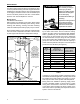
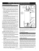
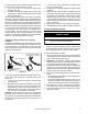
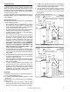
8. “Combo” Heating Systems require higher water
temperatures than other applications. When the
system is used to supply water for Combo Heating
applications, a means, such as mixing valve, must be
installed to temper the water in order to reduce scald
hazard potential (see Figure 11 & Figure 12).
Installation
The heating mode may be one of the following options:
A. A fan coil/air handler (Figure 11).
B. A hydronic baseboard (fi nned tube) loop/In fl oor heating
(Figure 12).
The following is a list of requirements for the installation
of option A or B.
1. Install shut-off valves and unions so that the water
heater can be isolated from the heating module should
servicing of the water heater become necessary.
2. Install a drain valve at the lowest point of the heating
loop so that water can be drained from the heating
module without affecting the water heater.
3. If the air handler does not have a venting means at
the highest point of the piping arrangement, install
an air bleed at the highest point of the plumbing
arrangement.
WATER
HEATER
8 in TO
12 in MAX.
HOT
OUTLET
EXPANSION TANK (OPTIONAL)
MIXING
VALVE
COLD INLET
CHECK VALVE (IF USED
REQUIRES EXPANSION TANK)
COLD SUPPLY
HOSE BIB
(OPT.)
FLOW
CONTROL
SUPPLY
RETURN
CHECK
VALVE
EXTERNAL
CIRCULATOR
AIR
HANDLER
HOT WATER
TO HOUSE
FIXTURE
C
H
M
INTERNAL
CIRCULATOR
DRAIN/
PURGE
VALVE
(see also
Massachusetts
code requirements
on pg 8)
Figure 11
WATER
HEATER
8 in TO
12 in MAX.
HOT
OUTLET
EXPANSION TANK (OPTIONAL)
MIXING
VALVE
COLD INLET
CHECK VALVE (IF USED
REQUIRES EXPANSION TANK)
COLD SUPPLY
HOSE BIB
(OPT.)
FLOW
CONTROL
SUPPLY
RETURN
CHECK
VALVE
EXTERNAL
CIRCULATOR
HOT WATER
TO HOUSE
FIXTURE
C
H
M
HYDRONIC
BASEBOARDS
(SERIES
CONNECTED
SHOWN)
(see also
Massachusetts
code requirements
on pg 8)
Figure 12