SIERRA PATIO COVER INSTALLATION INSTRUCTIONS Contact us at: 1-888-442-2928 or www.americana.com Before You Begin: Consult your local building department for any required permits You may be required to obtain a building permit for this structure. Contact your local building department for details. Read instructions thoroughly Please read all instructions and notes carefully prior to assembly. Americana is not responsible for replacing parts lost or damaged due to incorrect assembly.
Tools Needed for Installation Socket / Hex Head Driver Sizes: 1/4”, 5/16”, 3/8”, 7/16” Safety Glasses Tape Measure Electric Drill Screw Driver Flat & Phillips Drill Bit Sizes: 1/8”, 3/16”, 1/4”, 5/8” (optional) Ladder Carpenters Level Other Required Tools: Gloves, Chalk Line, Silicone Caulking Recommended Tools: Rubber Mallet, Carpenters Square, Pliers, Metal Hack Saw Installation Notes and Tips Complete site preparation before beginning assembly.
Table of Contents Safety Information……………………………………………………………………………..…. 4 Site Preparation………………………………………………………………………………….. 4 Parts……………………………………………………………………………………………..… 5 Optional Parts………………………………………………………………………………..…… 7 Mounting Channel Installation……………………………………………………………….…. 9 Standard Post Mounting Bracket Installation…………………………………………………. 13 Heavy-Duty Post Mounting Bracket Installation………………………………………………. 14 Buried Post Installation…………………………………………………………………………..
Safety Information Please read and understand this entire manual before attempting to assemble or install the product. The design of the shade structure as set forth herein pertains only to the components and assemblies as manufactured by Americana Building Products. The design of and attachment to supporting structural elements are outside the scope of this guide.
NOTE: Length and quantity of parts will vary based on the size of the awning. Parts List A D Awning Rail Part Code: 11610 B Header - 4” C Channel Part Code: 30151 G E Roof Panel - 10” V Style Part Code: 10104 Americana Building Products .
NOTE: Length and quantity of parts will vary based on the size of the awning. Parts List J (continued) Fascia Clip Part Code: 60615 K Fascia Hanging Bracket Part Code: 60629 L Roof Panel Flashing Plug Part Code: 60619 Screws shown actual size.
NOTE: Length and quantity of parts will vary based on the size of the awning. OPTIONAL Parts M Scupper Part Code: 90241 Mounting Channel Splice O Part Code: 60602 Column Mounting Bracket Decorative Column P Part Code: 60722 Q Part Code: 50131 Header - 3” Box Beam Header - 3” x 8” S Part Code: 11271 Americana Building Products C Channel Splice N Part Code: 60616 T Part Code: 11542 .
NOTE: Length and quantity of parts will vary based on the size of the awning. OPTIONAL Parts V (continued) Roof Panel - 8” Flat Style Part Code: 10206 Flat Panel Flashing Plug W Part Code: 60058 Aluminum Bird Plug X Part Code: 60625 3/8” x 3-1/2” Bolt KK Part Code: 20415 3/8” Hex Nut LL Part Code: 20562 Americana Building Products 1/4” Square Nut 1/4” x 3/4” Bolt NN Part Code: 20503 MM Part Code: 20751 .
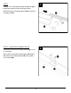
STEP 1 Mark a level line on the surface where the shade structure is to be mounted. Recommended 5-1/2” minimum above an out-swinging door or window. It is recommended that the front height of the shade structure be lower than the mounting height 1/2” per foot of projection. It is NOT recommended to install the shade structure completely flat. DO NOT direct drainage toward the back of the shade structure.
STEP 3 Using a 1/4” bit, drill holes through awning rail (A) to match hole spacing on the mounting surface. 3 Slide the hinge of mounting channel (B) into the slot of awning rail (A). STEP 4 - MOUNTING CHANNEL SPLICE Complete this step only if mounting channel (B) is in two or more pieces. 4 Apply caulk to mounting channel splice (N). Attach two pieces of mounting channel (B) using (4) #8 x 3/4” screws (AA). Americana Building Products .
STEP 5A - MOUNTING TO WOOD FRAME 5A Align the holes in awning rail (A) with the holes in the mounting surface. Attach awning rail (A) using 1/4” x 1-1/2” lag screws (GG) through each hole. STEP 5B - MOUNTING TO MASONRY Insert lag screw plug (HH) into each hole in the mounting surface. Align the holes in awning rail (A) with the holes in the mounting surface. Attach awning rail (A) using 1/4” x 1-1/2” lag screws (GG) into each lag screw plug (HH).
STEP 6 6 Apply a continuous bead of caulk along the back side of awning rail (A). STEP 7 Using chalk lines, mark the outline of the shade structure on the foundation. Mark the location of each post by subtracting the desired overhang from the overall dimensions. If layout drawings were received with your order, use those as the guide. If installing decorative columns (P), post spacing must match the pre-punched square holes in C channel header (D).
STEP 8A - STANDARD BRACKETS If you received the standard post mounting bracket (H), mark the location of the (4) holes in the bracket at a post location. Using a 3/16” bit, drill holes to match the pattern on the bracket. Remove dust from the holes and attach post mounting bracket (H) to the foundation using (4) 1/4” x 1-3/4” Tapcon anchors (II). 8A NOTE: If attaching to wood or composite deck, 1/4” x 1-1/2” lag screws (GG) must be used. DO NOT use Tapcon anchors to attach to wood or composite surface.
OPTIONAL STEP 8B - HEAVY-DUTY BRACKETS If you received the optional heavy-duty mounting brackets (R), mark the location of the (4) holes in the bracket at a post location. Anchor bolts 1/2” diameter must be purchased separately for use with this bracket. Follow the manufacturer’s guidelines for proper installation. Using a 7/16” bit, drill (4) holes through post (C) according to the dimensions shown.
OPTIONAL Note: Review Site Preparation on page 4 8C STEP 8C - BURIED POSTS If you plan to bury posts (C), consult your local building authorities for required footing diameter and depth. Dig footings to the required size at each post location. CAUTION: Before any digging, check with local utilities to determine the location of buried cables, pipes, etc. NOTE: A footing inspection is often required before pouring concrete. Consult your local building authorities.
STEP 8D - DECORATIVE COLUMNS 8D If installing decorative columns (P), mark the location of (2) column mounting brackets (Q) at a post location. Using a 3/16” bit, drill holes to match the pattern on the brackets. Remove dust from the holes and attach column mounting brackets (Q) to the foundation using (4) 1/4” x 1-3/4” Tapcon anchors (II). NOTE: If attaching to wood or composite deck, 1/4” x 1-1/2” lag screws (GG) must be used. DO NOT use Tapcon anchors to attach to wood or composite surface.
STEP 9 9A Depending on the header style received with your order, there are two header mounting bracket options. 4” C CHANNEL OR 3” BOX BEAM HEADER: Fit header mounting bracket (I) in the top of post (C) so that the back of the bracket faces away from the front of the cover. Have assistance hold the top of post (C) steady. Using a 1/8” bit, drill (4) pilot holes through the post and bracket, (2) on each side. Attach using (4) #12 x 1-1/4” screws (BB). Repeat for all posts (C).
STEP 10A - 4” C CHANNEL 10A Position header (D) over posts (C) with an equal amount of overhang on both ends. NOTE: If header (D) is in two or more pieces, be sure one end of the header is centered over a post. Complete splice installation below before attaching to posts. Attach header (D) to header mounting bracket (I) using (4) #12 x 1-1/4” screws (BB).
STEP 10B - 3” BOX BEAM 10B Position header (S) over posts (C) with an equal amount of overhang on both ends. NOTE: If header (S) is in two or more pieces, be sure one end of the header is centered over a post. Complete splice installation below before attaching to posts. Attach header (S) to header mounting bracket (I) using (4) #12 x 1-1/4” screws (BB).
STEP 10C - 3” x 8” HEADER 10C Position header (T) over posts (C) with an equal amount of overhang on both ends. NOTE: If header (T) is in two or more pieces, be sure one end of the header is centered over a post. Attach header (T) to header mounting bracket (U) using (12) #8 x 3/4” screws (AA). 10” ‘V’ style panel installation: Go to page 21 8” flat style panel installation: Go to page 23 Americana Building Products .
STEP 11 - 10” ‘V’ STYLE ROOF PANELS 11 Attach one roof panel (G) at each end of the cover before attaching other panels to ensure the cover stays square. Attach the formed end of roof panel (G) to mounting channel (B) using #8 x 1/2” bolt (DD), #8 hex nut (EE), and 1/2” washer (FF) through the pre-drilled holes. Insert roof panel flashing plug (L) between the roof panel (G) and mounting channel (B).
STEP 13 Position the lock of the next roof panel (G) over the lock of the previous panel. Snap the locks together by tapping the top with a rubber mallet along the length of the panel. If necessary, have assistance hold a spare 2x4 board under the locks. Slide the panel into mounting channel (B) until the front end is flush with the previous panel. Repeat steps 11-12 on page 21 to attach roof panel (G) to mounting channel (B) and the header.
STEP 11 - 8” FLAT STYLE ROOF PANELS 11 Attach one roof panel (V) at each end of the cover before attaching other panels to ensure the cover stays square. Attach the formed end of roof panel (V) to mounting channel (B) using (2) #8 x 1/2” bolts (DD), #8 hex nuts (EE), and 1/2” washers (FF) through the pre-drilled holes. Insert roof panel flashing plug (W) between the roof panel (V) and mounting channel (B).
STEP 13 13 Position the lock of the next roof panel (V) over the lock of the previous panel. Snap the locks together by hooking the locks and rolling the panel down. Slide the panel into mounting channel (B) until the front end is flush with the previous panel. Repeat steps 11-12 on page 23 to attach roof panel (V) to mounting channel (B) and the header. NOTE: It is very important to maintain the 8” dimension between the center of the locks of each roof panel (V).
The remaining steps are completed the same for 10” ‘V’ style roof panels (G) and 8” flat style roof panels (V). 10” ‘V’ style roof panels are shown. 15 STEP 15 Starting at one end, install front gutter (E) to each fascia clip (J) by fitting the upper lip of the gutter into the slot at the top of the clip. Roll front gutter (E) forward and lock the lower lip of the gutter between fascia clip (J) and roof panel (G).
STEP 16 Fit the front of side gutter (F) (the end without the bird block) into the fabricated corner of front gutter (E) by angling the back of side gutter (F) away from mounting channel (B). 16 Have assistance hold the front of side gutter (F) in place. Fit the upper lip of side gutter (F) over the top of mounting channel (B). The lower lip of side gutter (F) should fit below mounting channel (B).
STEP 18 From underneath the cover, attach side gutter (F) to mounting channel (B) using fascia hanging bracket (K) and (3) #8 x 3/4” screws (AA). 18 Repeat steps 16-18 for remaining side gutter (F). STEP 19 - SCUPPER INSTALLATION 19 If optional downspout kit was received with your order, you may not have received scupper (M). Follow the separate downspout assembly instructions attached. Determine the desired location to drain water from front gutter (E).
OPTIONAL BIRD PLUG INSTALLATION 20 Note: When installing bird plugs while installing roof panels, it is important NOT to completely tighten the screws attaching to the header. This will make it significantly easier to install the bird plugs. If installing bird plugs with the roof already completed, it may be necessary to loosen the screws attaching the roof panels to the header. Install (2) roof panels (G) according to the instructions on pages 21-22.
Care and Maintenance Every 12 months your shade structure should be inspected and maintained by: Tightening loose nuts and bolts at all connections. Repairing damage to the finish to prevent corrosion. Replacing lost or damaged fasteners, brackets, and other parts. Replacing brittle or cracked sealer to prevent leaks. Removing obstructions and miscellaneous build-up from gutters, eaves, and downspouts.
DOWNSPOUT ASSEMBLY INSTALLATION INSTRUCTIONS FOR PATIO COVERS AND CARPORTS STEP 1 Determine the desired location to drain water from the front gutter of the shade structure. The downspout is best positioned next to or in front of a post. Cut a hole no bigger than 1-1/2” diameter in the bottom of the gutter. Alternatively, you may drill several small holes in a rectangular pattern no bigger than 1-1/2” x 2-1/2”. STEP 2 Apply a generous bead of caulk around the flange of the downspout outlet.
DOWNSPOUT ASSEMBLY INSTALLATION INSTRUCTIONS FOR PATIO COVERS AND CARPORTS STEP 4 Cut the downspout tube to the desired length. Attach to the second elbow using (2) #8 x 3/4” screws. The tube should end approximately 6” from the ground. STEP 5 Evenly space the downspout straps along the downspout tube. Attach to the post using (3) #8 x 3/4” screws per strap. STEP 6 Attach a third downspout elbow to the end of the downspout tube facing away from the shade structure. Attach using (2) #8 x 3/4” screws.
STEP 22 - OPTIONAL SIDE PLATE INSTALLATION If not pre-drilled, use a 5/8” bit to drill holes through one side of side plate (Y) according to the dimensions shown. STEP 23 Center (2) side plates (Y) next to post (C). Attach side plate (Y) to post (C) and header (T) using #12 x 1-1/4” screws (BB) through each hole. Insert a 5/8” hole plug (OO) into all holes. 21 22 Repeat for each post (C). Americana Building Products .