
Specifications


fnstalfation IMl66-107
1.
2.
3.
4.
Mounting Procedure
Unpack and carefully inspect all equipment for
shipping damage. Notify the shipper immediately
of any damages found. Verify that the packages
contain all parts and accessories needed for proper
installation and operation.
If a backboard is required at the mounting location,
attach it securely to provide a stable mounting
surface for the equipment.
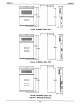
Refer to Figure 3-1 or to the PPO32-000 mounting
template included in the literature that
accompanies the common equipment cabinet for
the locating dimensions required for the three
mounting screws, and mark their locations on the
mounting surface.
Drill holes in the mounting surface of a proper size
to accommodate the hardware being used. If
necessary, prepare these holes with inserts,
anchors or other attachment devices as dictated by
the type of mounting surface.
5.
6.
7.
a.
Insert the two top screws into the mounting surface
and tighten them to within approximately
l/8-inch
of the surface.
Hang the cabinet on the top screws using the
mounting holes located on the rear of the cabinet.
Note that these holes are elongated with an
enlargement at one end. This feature allows the
cabinet to snap down on the screws to secure the
mounting when the cabinet is hung on them.
insert a third screw through the mounting tab
located on the lower edge of the cabinet and into
the mounting surface, and tighten it into place.
Place the individual telephone stations as desired
and in keeping with accepted industry and off ice
standards. A telephone station can be wall
mounted if necessary as they are desk/wall
reversible. Refer to Chapter 6, Maintenance, for
instructions in preparing a desk/wall reversible
station for wail mounting.
3-2