
Specifications


Installation
IMl66-107
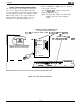
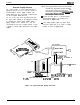
Power Failure Station Connections
The system provides a tip and ring pair connected to
line 1 as an emergency power failure circuit. This
circuit is active during a commercial AC power failure if
an external battery assembly is not installed to provide
battery back-up power to the system. Connect an
industry standard, single-line telephone, such as a
model 2500, to a power failure pair.and use it to
provide communications capability until the
AC
power
to the system is restored.
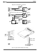
The power failure.pair is located as follows and as
detailed in
Figure 3-7
below.
NOTE: The system also provides one power failure
connection with each add-on expansion
module.
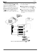
POWER FAILURE TERMINALS ON
STATION CONNECTOR BLOCK
I4-LINE,
8-STATION AND 8-LINE,
I6-STATION
BASE
UNITS1
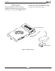
TYPICAL INDUSTRY STANDARD
NON-ELECTRIC TELEPHONE
(POWER FAILURE INTERFACE1
-
-
Gf
PJ
/
gj--1-w
34 --l--
35 --l--
36
--l--
37--i--
36
--1--
39
--l--
40 --l--
41----c-
42--t--
43---I--
44 --I--
45 --l--
46--l--
47 --I--
46--I--
49--l--
SO--l--
CLIP TERMINALS
-OR-
POWER FAILURE JACK
lI6-LINE,
32-STATION
BASE
UN111
Figure 3-7. Power Failure Connection
3-22