
Use and Care Manual


4
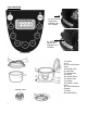
PARTS DIAGRAM
An “EXTERNAL”
Locking Pin
Indicates Lid is
NOT locked
Control Panel
1) Handle
2) Lid
3) Pressure Release
Valve
4) Floating Valve
6) Inner tank
7) Locking Ring
8) Handle
10) Control Panel
11) Power Cord
13) Handle
15) Stainless Steel
Case
16) Internal Heating
Element
17) Base
20) Sealing Ring
Floating Valve
An “INTERNAL”
Locking Pin
Indicates Lid is
LOCKED