
Instructions / Assembly


Page A6
7/07
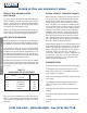
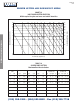
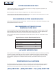
PROPER GUTTER AND DOWNSPOUT SIZING
TYPE AREA “A” Nominal Actual
Size Size
Plain sq.in. sq.mm. sq.in sq.mm. in. mm. in. mm.
Round 7.07 4560 5.94 3831 3 76 3 76
12.57 810 11.04 7120 4 102 4 102
19.63 12661 17.71 11422 5 127 5 127
28.27 18234 25.95 16737 6 152 6 152
50.24 32404 47.15 30411 8 203 8 203
Corrugated 5.94 3831 3 76 3 76
Round 11.04 7120 4 102 4 102
17.72 11429 5 127 5 127
25.97 16750 6 152 6 152
Plain 3.94 2541 3.00 1935 2 51 1.75x225 44x57
Rectangular 6.00 3870 4.80 3096 3 76 2x3 51x76
12.00 7740 10.31 6649 4 102 3x4 76x102
20.00 12900 15.75 10158 5 127 3.75x4.75 95x121
24.00 15480 21.56 13906 6 152 4x6 102x152
Rectangular 3.80 2451 3.00 1935 2 51 1.75x2.25 44x57
Corrugated 7.73 4985 6.38 4155 3 76 2.37x3.25 60x83
11.70 7621 10.00 6513 4 102 2.75x4.25 70x108
18.75 12213 16.63 10832 5 127 3.75x5 95x127
“A” = area of 1/4 in.(6.4 mm) undersized inlet See Figures 1-31 and 1-32 for gage
TABLE 1-3
DIMENSIONS OF STANDARD DOWNSPOUTS
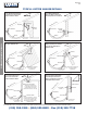
7. Assuming that using the fewest number of downspouts
is desirable, their locations will be affected by
a. gutter capacity and length. To limit the effects of ther-
mal expansion in gutters 50 ft(15.3 m) is a practical maxi-
mum length of gutter to be served by a downspout. Unless
special provisions are made for flexibility in downspouts,
gutters and their support systems, gutters should expand
away from downspouts and downspouts should not be lo-
cated near gutter expansion joints. See expansion coefficients
in Appendix A-1 and expansion allowances in Figures 1-5 to 1-10.
b. the capacity of the inlet tube. See Table 1-3 and Figure
1-33. Also, a sharp bend at the inlet may clog.
c. potential for water freezing in downspouts and gut-
ters. Open, partially open or corrugated styles downspouts
are suggested for areas subject to icing. Locating down-
spouts on the north side of buildings is not recommended
for such areas.
d. the appearance of the downspout system and a poten-
tial need for concealment. See Figures 1-31 and 1-32.
e. the greater capacity of a pitched gutter.
f. the downspout discharge location. Water disposal at
this location should be acceptable. See Figures 1-31 and 1-36.
g. the risk of gutter overflow from insufficient drainage
capacity. See Figures 1-4, 1-21, and 1-23.
h. a scupper serving a designated roof area. See Figures
1-26 to 1-30.
After the number and location of downspouts have been
determined, the areas to be drained by each downspout
should be figured. In making this calculation for a pitched
roof, the plan area should be adjusted according to recom-
mendations given on Table 1-1.
SAMPLE PROBLEM: Select downspouts for a building in
Boston, Mass. The building is 100 x 85 ft.(30.5 x 26 m) with
a double pitched roof having a slope of 6 in./ft.(152 mm/m).
The slope is toward the 100 ft.(30.5 m) side. Maximum rain-
fall conditions will be used to determine downspout size.
It is decided to drain the building with 4 downspouts located
at each corner of the building. An expansion joint will be
installed in each gutter between the downspouts.
The plan area of this building is 8500 sq ft.(790 sq m). Since
the slope is 6 in./ft.(152 mm/m), factor 1.10 is used (Table
1-1), making the design area 9350 sq ft.(868 sq m). Thus
each of the four downspouts will serve a 2338 sq ft.(217 sq
m) area. From column B, Table 1-2, opposite Boston, it is
found that 1 sq in.(645 sq mm) of downspout will drain 170
sq ft.(16 sq m) of roof area. Divide 2338(217) by 170(16) to
determine that each downspout should have a minimum area
of 13.56 sq in.(8746 sq mm).
From Table 1-3, it is found that there is a choice of; a 5 in.
(127 mm) Plain Round, a 5 in.(127 mm) Corrugated Round,
a 5 in.(127 mm)
Rectangular Corrugated, or 5 in.(127 mm)
Plain Rectangular downspout.
(215) 355-1200 • (800) 523-8852 • Fax (215) 355-7738
XIDNEPPA ECNEREFER LACINHCET
®