
Instructions / Assembly


Page A3
7/07
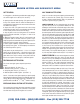
PROPER GUTTER AND DOWNSPOUT SIZING
RAINFALL INTENSITY - DOWNSPOUT CAPACITY
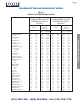
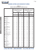
Rainfall intensity is usually given in inches per hour for a
five minute duration or one hour duration based on U.S.
Weather Bureau records. Table 1-2 based on records
through 1978, gives five minute intensities for selected
cities. New Orleans, Los Angeles, for example, may have
8 in./hr.(203 mm/hr) for a five minute duration yet record
only 4.8 in. (121 mm) in an hour over a 100 year period.
These rates correspond to 0.133 in./min.(3.4 mm/min.)
and 0.08 in./min.(2 mm/min.). Local codes may require
that drainage systems only be designed for the latter. It
takes 96.15 square feet(8.93 square meters) of surface
with 1 inch per hour(25 mm/hr) of water to correspond
with 1 gpm (0.063 l/s) flow rate. Downspouts and gutters
are sized in relation to rainfall on this basis.
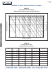
Plumbing codes typically use the vertically projected roof
area for drainage design and they often use a square foot
allowance per square inch of downspout for 1 in./hr.(25
mm/hr) rainfall that varies with diameter, for example, 3
in.(76 mm): 911(85); 4 in.(102 mm): 1100 (102); 5
in.(127 mm): 1280 (119); 6 in.(152 mm): 1400 (130) and
8 in.(203 mm): 1750 (163) sq. ft.(sq. m). Net drainage
capacity from using Table 1-1 and 1-2 should be com-
pared with local code requirements.
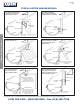
DOWNSPOUT SIZING
In sizing downspouts, the following considerations apply:
1. Downspouts of less than 7.00 sq in.(4515 sq mm)
cross section should not be used except for small areas
such as porches and canopies.
2. The size of the downspout should be constant through-
out its length.
3. Downspouts should be constructed with conductor
heads every 40 ft(12.2 m) to admit air and prevent
vacuum.
4. Offset of more than 10 ft(3.0 m) can affect drainage
capacity.
5. The gutter outlet capacity should suit the downspout
capacity.
6. The downspout size must suit the bottom width of the
gutter.
DESIGN OF ROOF DRAINAGE SYSTEMS
ROOF DRAINAGE
The roof is one of the most essential parts of a building as it
protects occupants, contents, and interior of the structure
from the elements. Once an architect has determined the
kind of roof he intends to use, he must give equal attention
to the design of the roof drainage system.
Factors to be considered in the design of roof drainage sys-
tems are the area to be drained, size of gutters, downspouts,
outlets, slope of roof, type of building, and appearance.
ROOF AREA TO BE CONSIDERED
The design capacity for a roof drainage system depends on
the quantity of water to be handled. The quantity of water in
turn depends on the roof area, slope, and rainfall intensity.
In considering the roof area, it must be remembered that
rain does not necessarily fall vertically and that maximum
conditions exist only when rain falls perpendicular to a sur-
face. Since the roof area would increase as its pitch increases,
then it would not be advisable to use the plan area of a pitched
roof in the calculation of a drainage system.
Experience has taught that use of the true area of a pitched
roof often leads to oversizing of
gutters, downspouts, and
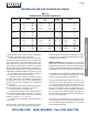
drains. To determine the design area for a pitched roof, Table
1-1 is used.
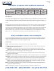
* To determine the design area multiply the plan area by the factor in B column
These areas are then divided by the proper factor given in
Table 1-2, thus obtaining the required area in square inches
(square mm) for each downspout. From Table 1-3 select the
downspout.
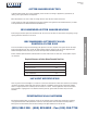
TABLE 1-1
DESIGN AREAS FOR PITCHED ROOFS
PITCH *B
in./ft. mm/mm
Level to 3 76/305 1.00
4 to 5 102-127/305 1.05
6 to 8 152-203/305 1.10
9 to 11 229-279/305 1.20
12 305/305 1.30
(215) 355-1200 • (800) 523-8852 • Fax (215) 355-7738
XIDNEPPA ECNEREFER LACINHCET
®