
Sizing Guide


14
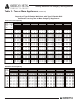
Venting Guidelines for Category I Gas Appliances
Two or More Appliances - Tables 3 and 4 (continued)
10. The connector rise (R) for each appliance connector shall be measured from the draft hood outlet or
flue collar to the centerline where the vent gas streams come together.
11. For multiple units of gas utilization equipment all located on one floor, available total height (H) shall
be measured from the highest draft hood outlet or flue collar up to the level of the outlet of the
common vent.
NOTE: For multistory installations, refer to the National Fuel Gas Code.
12. Where two or more appliances are connected to a vertical vent or chimney, the flow area of the
largest section of vertical vent or chimney shall not exceed seven times the smallest listed appliance
categorized vent areas, flue collar area, or draft hood outlet area, unless designed in accordance with
approved engineering methods.
13. For appliances with more than one input rate, the minimum vent connector capacity (FAN Min)
determined from the tables shall be less than the lowest appliance input rating, and the maximum vent
connector capacity (FAN Max or NAT Max) determined from the tables shall be greater than the
highest appliance input rating.
14. Listed, corrugated metallic chimney liner systems in masonry chimneys shall be sized by using
Tables 3 and 4 for Type B vents, with the maximum capacity reduced by 20 percent (0.80 x maximum
capacity) and the minimum capacity as shown in these tables. Corrugated metallic liner systems
installed with bends or offsets shall have their maximum capacity further reduced in accordance with
Paragraph 6 (see NFPA 54 for more information).
Figure 7
Example: Manifolded Common Vent Connector L
M
shall be no greater
than 1½ feet for each inch of manifold diameter; i.e., a 4-inch inside
diameter common vent connector manifold shall not exceed 6 feet in
length.
Note: This is an illustration of a typical manifolded vent connector.
Different appliance, vent connector, or common vent types are
possible. Consult the notes for common venting.
Figure 8
Example: Offset Common Vent
Note: This is an illustration of a typical offset vent. Different
appliance, vent connector, or vent types are possible.
Consult the notes for a single appliance and common
venting.