5580500COM Nightstand B345580500COM0 Date of Purchase ___ / ___ / ___ Lot Number: THIS INSTRUCTION BOOKLET CONTAINS IMPORTANT SAFETY INFORMATION. PLEASE READ AND KEEP FOR FUTURE REFERENCE. Do Not Return This Product! Contact our customer service team for help first. Call: 1-800-489-3351 (toll free) Monday-Friday 9am - 5pm CST Visit: www.ameriwoodhome.com WARNING - Unit can tip over causing severe injury or death. - Anchor unit to stud in wall (if instructed to).
Contact Us! Do NOT return this product! Contact our friendly customer service team first for help. Assembly Tips Call us! 1-800-489-3351 Monday-Friday 9am - 5pm CST Visit ameriwoodhome.com to view the limited warranty valid in the U.S. and Canada. You Tube Helpful Hints PEOPLE NEEDED FOR ASSEMBLY: 1-2 ESTIMATED ASSEMBLY TIME: 1 HOUR - Open your item in the area you plan to keep it to avoid excessive heavy lifting. - Identify, sort and count the parts before attempting assembly.
k Quic bly em Ass Tip Before You Start P P P P P Read through each step carefully and follow the proper order Separate and count all your parts and hardware Give yourself enough room for the assembly process Have the following tools: Flat Head Screwdriver, #2 Phillips Head Screwdriver and Hammer Caution: If using a power drill or power screwdriver for screwing, please be aware to slow down and stop when screw is tight. Failure to do so may result in stripping the screw.
Board Identification Not actual size B A Left Panel 35580340010 Right Panel 35580340020 J Front Vertical Molding (2) 35580340100 O Side Rail (4) 35580340150 Front Base 35580340060 K Rear Vertical Molding (2) 35580340110 P Apron 35580340160 ameriwoodhome.
Board Identification Not actual size T Back 35580340200 C R T K O S Q J P O O K E B A J D O H I F G ameriwoodhome.
Board Identification Not actual size DWR SIDE DWR BACK N M DWR SIDE L ameriwoodhome.
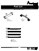
Part List Actual Size 3 1 2 (x17) #A22620 cam lock 4 (x4) #A22920 (x17) #A22610 connector cam bolt 7 bolt (x4) #A21660 wood dowel 12 (x6) #A23030 confirmat screw connector bolt (x20) #A12950 #8x1-1/8" screw 13 (x4) #A21550 5x50 wood dowel ameriwoodhome.
Part List Not actual size 16 17 (x1) #A50875 (x2) #A54510 handle drawer bracket 18a Left Cabinet Member 18b Right Cabinet Member 18c Left Drawer Member 18d Right Drawer Member (x1) 18 #A56750 drawer slide ameriwoodhome.
STEP 1 Using screw (9), attach the front vertical molding (J) and rear vertical molding (K) to the left panel (A). 9 Please be sure to screw into the surface of the front vertical with the pilot holes. Do not fully tighten the screws until next step is completed. (x6) #A12950 Pilot hole in front vertical molding. 9 J 9 9 A K 9 9 9 ameriwoodhome.
STEP 2 9 Using screw (9), attach the side rails (O) to the left panel (A). (x4) #A12950 Now tighten the screws that were left loose in the previous step. O 9 J 9 A 9 O K 9 ameriwoodhome.
STEP 3 1 2 marked with a "L" 18a 5 (x2) #A22620 (x1) #A22610 (x1) #A56750 (3) #A11080 5 5 1 5 A 2 1 5 Quick Assembly Tip 18a Proper orientation of CAM LOCK ameriwoodhome.
STEP 4 9 Using screw (9), attach the front vertical molding (J) and rear vertical molding (K) to the right panel (B). Please be sure to screw into the surface of the front vertical with the pilot holes. Do not fully tighten the screws until next step is completed. Pilot hole in front vertical molding. (x6) #A12950 J 9 B K 9 ameriwoodhome.
STEP 5 9 Using screw (9), attach the side rails (O) to the right panel (B). Now tighten the screws that were left loose in the previous step. (x4) #A12950 O 9 J B 9 O 9 9 K ameriwoodhome.
STEP 6 1 18b 2 5 (x2) #A22620 (x1) #A22610 marked with a "R" (x1) #A56750 (3) #A11080 5 5 1 5 B 2 1 5 Quick Assembly Tip 18b Proper orientation of CAM LOCK ameriwoodhome.
STEP 7 1 8 (x2) #A22620 (x2) #A21660 Quick Assembly 1 Tip Proper orientation of CAM LOCK 8 1 E 8 ameriwoodhome.
STEP 8 12 (x2) #A23030 A 12 D 12 ameriwoodhome.
STEP 9 UNLOCK A LOCK E D ameriwoodhome.
STEP 10 Place the right panel assembly as shown and tighten the cam lock (1). Attach the right panel (B) to the bottom (D) using 2 screws (12). 12 (x2) #A23030 UNLOCK A LOCK E D 12 B 12 ameriwoodhome.
STEP 11 Insert four long wood dowels (13) into the larger holes in the top (C). Press the upper side moldings (Q) and (R) onto the wood dowels (13) and press until seated onto the top (C). Fasten to the top (C) with screws (10) as shown. Position the upper front molding (S) as shown and attach with screws (10). 13 10 (x7) #A13020 (x4) #A21550 10 Be sure to use the holes shown. 10 10 Q 13 10 13 10 10 R S 10 C 13 ameriwoodhome.
STEP 12 2 11 6 (x6) #A22610 (x4) #A12120 (x2) #A53600 6 11 6 2 P R S 2 2 C 2 2 Q 2 ameriwoodhome.
STEP 13 1 8 Quick Assembly Tip (x2) #A22620 (x2) #A21660 Proper orientation of CAM LOCK 1 T 8 1 8 ameriwoodhome.
STEP 14 12 (x2) #A23030 D T 12 ameriwoodhome.
STEP 15 UNLOCK LOCK P A C B ameriwoodhome.
STEP 16 3 1 2 (x4) #A22620 (x4) #A22610 (x4) #A22920 2 1 Quick Assembly Tip G 3 2 Proper orientation of CAM LOCK 1 H 3 Position the connector as shown before inserting. You will need to use a hammer to fully insert. ameriwoodhome.
STEP 17 1 (x4) #A22620 2 6 11 (x6) #A12120 (x4) #A22610 (x6) #A53600 1 6 11 I 2 6 1 11 F Quick Assembly Tip ameriwoodhome.
STEP 18 4 (x4) #A22910 Carefully flip the unit over and set it on it's top. 4 4 4 D 4 ameriwoodhome.
STEP 19 Press the right side base (H) onto the bottom (D) so the connectors (3) engage the connector bolts (4). Turn the screw in the connector clockwise to lock in place. 3 Turn screw clockwise to lock in place. H D ameriwoodhome.
STEP 20 6 (x3) #A12120 UNLOCK Attach the rear base (I) to the right base (H) as shown. Then attach the rear base (I) to the bottom (D) using screws (6). LOCK 6 H I D ameriwoodhome.
STEP 21 UNLOCK LOCK Press the left side base (G) onto the rear base as shown making sure the connectors (3) in the left side base engage the connector bolt (4) in the bottom (D). Securely fasten the cam lock (1) and connectors (3). G I 3 D Turn screw clockwise to lock in place. ameriwoodhome.
STEP 22 6 UNLOCK (x3) #A12120 LOCK Secure the front base (F) to the left side base (G) and right side base (H) as shown, then secure to the bottom (D) with three screws (6). 6 F H D G ameriwoodhome.
STEP 23 16 2 6 (x1) #A22610 (x2) #A54510 (x4) #A12120 2 6 6 6 M 6 ameriwoodhome.
STEP 24 15 1 Quick 6 (x1) #A22620 Assembly Tip (x4) #A12120 (x1) #A21520 Proper orientation of CAM LOCK 15 L 1 DWR SIDE 6 6 L DWR SIDE M 6 6 ameriwoodhome.
STEP 25 unfinished surface N DWR SIDE L DWR SIDE M ameriwoodhome.
STEP 26 14 (x6) #A21970 14 14 14 14 DWR BACK 14 DWR SIDE N 14 DWR SIDE ameriwoodhome.
STEP 27 7 marked with "L" 18c 5 (x4) #A11080 marked with "R" 18d (x2) #A17250 (x1) #A56750 17 18d (x1) #A50875 5 5 DWR BACK DWR SIDE 18c N 5 DWR SIDE 5 7 7 M 17 Attach handle after installing the drawer slides. ameriwoodhome.
STEP 28 cabinet member Note: The drawer bracket holes are slotted. Drawer front can be adjusted by loosening screws, making needed adjustments and retightening screws. ameriwoodhome.
Maximum Loads This unit has been designed to support the maximum loads shown. Exceeding these load limits could cause sagging, instability, product collapse, and/or serious injury. 40 lbs 18.2 kg 15 lbs 6.8 kg 40 lbs 18.2 kg Warning: Risk of injury to persons - do not place a television on this furniture. This furniture is not approved for use with a television. Certificate of Conformity 1. This certificate applies to the Dorel Home Furnishings, Inc. product identified by this instruction manual. 2.
Register your product to receive the following: * New trend details - sneak peek on what's new * Surveys - have a voice within our community * Exclusive deals and discount codes * Quick and easy replacement part service To register your product, visit ameriwoodhome.
Español Cubierta Delantera Este libro de instrucciones contiene información IMPORTANTE de seguridad. Por favor lea y manténgalo para referencia en el futuro. No Regrese este producto! Comuniquese con nuestro amistoso equipo de servicio al cliente para obtener ayuda. Llamenos al: 1-800-489-3351 (Gratis) Lunes - Viernes 9am - 5pm CST Visitar: www.ameriwoodhome.com PRECAUCION Este mueble puede volcarse y causar graves heridas y/o muerte. Anclar el mueble a un poste de madera en la pared (si esto se requiere).
Español Página 9 Fije la moldura vertical delantera (J) y la moldura vertical trasera (K) al panel izquierdo (A) con el tornillo (9). Asegúrese de atornillar en la superficie de la moldura vertical delantera con los agujeros guía. Página 10 Fije los rieles laterales (O) al panel izquierdo (A) con el tornillo (9). Página 12 Fije la moldura vertical delantera (J) y la moldura vertical trasera (K) al panel derecho (B) con el tornillo (9).
Español Página 29 Presione la base del lado izquierdo (G) sobre la base trasera como se muestra en la figura, asegurándose de que los conectores (3) en la base del lado izquierdo enganchen el perno del conector (4) en la parte inferior (D). Asegure firmemente el seguro de leva (1) y los conectores (3). Página 30 Asegure la base delantera (F) a la base del lado izquierdo (G) y a la base del lado derecho (H) como se muestra en la figura. A continuación, asegure a la parte inferior (D) con tres tornillos (6).
Français Couverture Avant CE LIVRET D'INSTRUCTION CONTIENT DES INFORMATIONS IMPORTANTES SUR LA SÉCURITÉ. VEUILLEZ LIRE ET GARDER POUR UNE RÉFÉRENCE FUTURE Ne retournez pas ce produit! Contactez notre équipe de service à la clientèle amicale d'abord pour obtenir de l'aide. Appelez-nous: 1-800-489-3351 (sans frais) du Lundi au Vendredi de 9h à 17h Heure Centrale Visitez: www.ameriwoodhome.com ATTENTION Le meuble peut basculer et causer des blessures graves ou la mort.
Français Page 9 En utilisant une vis (9), joignez la moulure verticale avant (J) et la moulure verticale arrière (K) au panneau de gauche (A). Assurez vous de visser à l'intérieur de la surface de l'élément vertical avant en utilisant les trous de guidage. Page 10 En utilisant une vis (9), fixez les rampes latérales (O) au panneau de gauche (A). Page 12 En utilisant une vis (9), fixez la moulure verticale avant (J) et la moulure verticale arrière (K) to au panneau de droite (B).
Français Page 29 Pressez la base latérale gauche (G) sur la base arrière tel que montré sur le schéma vous assurant que les connecteurs (3) de la base latérale gauche s'engagent dans le boulon de connexion (4) dans le fond (D). Resserrez la serrure à levier (1) et les connecteurs (3) pour sécuriser. Page 30 Sécurisez la base avant (F) sur la base latérale gauche (G) et la base latérale droite (H) tel que montré sur le schéma, puis sécurisez sur le fond (D) avec trois vis (6).