5362222COM 5 Drawer Dresser B345362222COM0 Date of Purchase ___ / ___ / ___ Lot Number: THIS INSTRUCTION BOOKLET CONTAINS IMPORTANT SAFETY INFORMATION. PLEASE READ AND KEEP FOR FUTURE REFERENCE. Do Not Return This Product! Contact our customer service team for help first. Call: 1‐800‐489‐3351 (toll free) Monday‐Friday 9am ‐ 5pm CST Visit: www.ameriwoodhome.com WARNING ‐ Unit can tip over causing severe injury or death. ‐ Anchor unit to stud in wall (if instructed to).
Contact Us! Do NOT return this product! Contact our friendly customer service team first for help. Assembly Tips Call us! 1‐800‐489‐3351 Monday‐Friday 9am ‐ 5pm CST Visit ameriwoodhome.com to view the limited warranty valid in the U.S. and Canada. You Tube Helpful Hints PEOPLE NEEDED FOR ASSEMBLY: 1‐2 ESTIMATED ASSEMBLY TIME: 2 HOURS ‐ Open your item in the area you plan to keep it to avoid excessive heavy lifting. ‐ Identify, sort and count the parts before attempting assembly.
k Quic bly em Ass Ti p Before You Start Read through each step carefully and follow the proper order Separate and count all your parts and hardware Give yourself enough room for the assembly process Have the following tools: Flat Head Screwdriver, #2 Phillips Head Screwdriver and Hammer Caution: If using a power drill or power screwdriver for screwing, please be aware to slow down and stop when screw is tight. Failure to do so may result in stripping the screw.
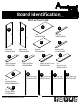
Board Identification Not actual size C B A E Top 35362222030 Top Rail 35362222050 F D Left Panel 35362222010 Right Panel 35362222020 Bottom 35362000040 I H G Upper Support 35362222070 Lower Support 35362000080 K x5 Drawer Bottom 39991340063910D N Right Front Leg 35362222140 L x5 Drawer Brace 35538000121 ameriwoodhome.
Board Identification Not actual size DWR BACK DWR SIDE x2 Drawer Side (small) 39991120346200C x1 Drawer Back (small) 39991120062950B This piece is paperboard construction. It is not made from wood, but is required for the assembly of your unit. Q DWR BACK DWR SIDE x8 Drawer Side (large) 39991167346200C This piece is paperboard construction. It is not made from wood, but is required for the assembly of your unit.
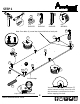
Part List Actual Size 2 3 1 (x17) #A22570 cam lock 5 4 (x17) #A22510 cam bolt (x12) #A21660 wood dowel (x50) #A11080 #6 x 7/16" flat head (x68) #A12120 #8 x 7/16" pan head 10 6 7 8 (x12) #A22910 connector bolt (x12) #A22920 connector 11 (x10) #A17400 8‐32 x 7/8" truss (x6) #A53600 angle bracket 12 (x30) #A21970 drive fastener ameriwoodhome.
Part List Not Actual Size 13a Left Cabinet Member 14a 13b 14c 14d Right Cabinet Member 14b 13c Left Drawer Member 13d #A84050 safety bracket kit Right Drawer Member (x5) #A56750 drawer slide pkg. 16 17 15 (x2) #A54510 drawer bracket (small) ameriwoodhome.
STEP 1 1 (x2) #A22570 7 3 2 (x4) #A22510 (x2) #A21660 (x6) #A22920 2 Note: Cam bolts (2) screw into the outside hole of each pair. 7 7 2 7 1 2 7 A 1 2 7 7 3 finished edge Quick Assembly 3 Tip Proper orientation of CAM LOCK ameriwoodhome.com 8 You will need to tap the connector (7) with a hammer to fully insert. Be sure the connector is positioned as shown before tapping into hole.
STEP 2 1 (x2) #A22570 2 7 3 2 (x4) #A22510 (x2) #A21660 (x6) #A22920 Note: Cam bolts (2) screw into the outside hole of each pair. 7 2 7 7 1 2 B 7 7 7 2 7 finished edge 1 3 Quick Assembly Tip You will need to tap the connector (7) with a hammer to fully insert. Be sure the connector is positioned as shown before tapping into hole. ameriwoodhome.
STEP 3 6 (x12) #A22910 Note: The rear legs (O&P) have small pilot holes on the back surface. 6 6 6 6 6 6 O 6 6 6 P 6 N 6 M ameriwoodhome.
STEP 4 With the help of another person, press legs (M&O) against the left panel (A) as shown so the connector bolt (6) engages the connector (7). Turn the screw in the center of the connector (7) clockwise to lock in place. 6 7 Turn screw clockwise to lock in place. O A M Note: For ease of leg attachment, place a piece of end foam (packaging material) under both ends of the left panel (A). A end view O ameriwoodhome.com Packaging foam from carton.
STEP 5 4 marked with a "L" 13a Left Cabinet Member (x15) #A11080 (x5) #A56750 13a 13a O 13a A 13a 13a M 4 13a ameriwoodhome.
STEP 6 With the help of another person, press legs (N&P) against the right panel (B) as shown so the connector bolt (6) engages the connector (7). Turn the screw in the center of the connector (7) clockwise to lock in place. Turn screw clockwise to lock in place. 6 7 P B N Note: For ease of leg attachment, place a piece of end foam (packaging material) under both ends of the right panel (B). B N Packaging foam from carton. ameriwoodhome.
STEP 7 marked with a "R" 13b 4 Right Cabinet Member (x15) #A11080 (x5) #A56750 13b 13b P 13b 13b N 4 13b ameriwoodhome.
STEP 8 5 2 (x4) #A22510 14a 8 (x6) #A12120 14b #A84050 safety bracket kit (x3) #A53600 5 finished edge 8 2 5 2 E C 2 14b 2 14a ameriwoodhome.
STEP 9 Quick 3 Assembly 1 Tip (x4) #A22570 (x4) #A21660 Proper orientation of CAM LOCK 1 3 1 1 3 D 1 3 3 ameriwoodhome.
STEP 10 5 8 (x6) (x3) #A53600 #A12120 Turn the part over from the previous step so the top surface faces up. Note, the bottom surface has the cam locks (1) in it. 5 Do not fully tighten the screws (5) going into the bottom rail (F) at this time. F finished edge 8 5 F D Cam locks (1) in bottom surface. ameriwoodhome.
STEP 11 Quick 3 Assembly 1 (x4) #A22570 Tip Proper orientation of CAM LOCK (x4) #A21660 1 3 1 G 1 3 H 1 3 3 ameriwoodhome.
STEP 12 UNLOCK A H D ameriwoodhome.
STEP 13 LOCK UNLOCK G B H A F D After right panel (B) is attached, make sure the bottom edge of the bottom rail (F) is even with the bottom edges of panels A & B. Now tighten the screws that were left loose in step 10. F B ameriwoodhome.
STEP 14 UNLOCK E C B A ameriwoodhome.
STEP 15 5 (x16) #A12120 9 (x12) #A21110 IMPORTANT! THE BACK PANEL IS A STRUCTURAL PART OF THIS UNIT AND MUST BE INSTALLED PROPERLY. With the help of another person, turn the unit over on its front side. Positon back panel as shown. Align squarely with outer edges. Attach back panel to rear legs (O&P) with screws (5) but do not tighten. Flush bottom edge of back panel with bottom edge of the bottom and nail straight into back edges of top (C) and bottom (D). Now tighten the screws (5).
STEP 16 16 2 15 5 (x20) #A12120 (x5) #A22510 (x2) #A54510 (small) (x8) #A54520 (large) 5 5 2 15 I 5 5 5 5 15 16 J x4 2 5 5 16 Note: Small brackets (15) goes on the upper drawer front (I) and large brackets (16) goes on the drawer front (J). ameriwoodhome.
STEP 17 Be sure the grooves in the drawer sides are centered with the groove in the drawer fronts. 5 (x20) #A12120 DWR SIDE 5 5 I DWR SIDE DWR SIDE 5 5 5 5 J x4 DWR SIDE 5 5 ameriwoodhome.com Note: You will be assembling 4 larger drawers.
STEP 18 Quick 10 Assembly 1 Tip (x5) #A21520 (x5) #A22570 Proper orientation of CAM LOCK Tap compression dowel (10) lightly with a hammer to insert. 1 L x5 10 ameriwoodhome.
STEP 19 UNLOCK DWR SIDE L I DWR SIDE DWR SIDE L J DWR SIDE x4 ameriwoodhome.
STEP 20 Insert a drawer bottom (K) into the groove of the drawer sides and drawer front as shown. raw surface K L DWR SIDE x5 ameriwoodhome.
STEP 21 12 You will need to tap the drive fasteners (12) with a hammer to securely fasten. 12 (x30) #A21970 Note: The smaller drawer back goes on the smaller drawer. 12 DWR SIDE DWR BACK 12 L 12 12 I DWR SIDE 12 DWR SIDE DWR BACK L 12 12 DWR SIDE J x4 ameriwoodhome.
STEP 22 11 13c 4 Left Drawer Member 13d (x20) #A11080 (x10) #A17400 17 Right Drawer Member (x5) #A56750 (x5) #52925 marked with a "R" Attach the slides first then the handle. 4 DWR SIDE marked with a "L" 11 DWR SIDE 4 11 x5 13c 17 ameriwoodhome.
STEP 23 14c 14d For Masonry, Concrete, or other wall materials: Consult your local hardware store for appropriate anchors to securely attach the safety bracket. #A84050 safety bracket kit IMPORTANT: THIS UNIT MUST BE SECURE TO THE WALL TO HELP PREVENT TIPOVER. FOLLOW THESE INSTRUCTIONS TO INSTALL THE ANTI‐TIPPING SAFETY BRACKET PROVIDED WITH THIS PRODUCT. WARNING hole Serious or fatal crushing injuries can occur from furniture tipover.
STEP 24 Note: The drawer bracket holes are slotted. Drawer fronts can be adjusted by loosening screws, making needed adjustments and retightening screws. I J J J cabinet member J roller drawer runner roller ameriwoodhome.
Maximum Loads This unit has been designed to support the maximum loads shown. Exceeding these load limits could cause sagging, instability, product collapse, and/or serious injury. 35 lbs 15.8 kg (each drawer) 50 lbs 22.6 kg Warning: Risk of injury to persons ‐ do not place a television on this furniture. This furniture is not approved for use with a television. Certificate of Conformity 1. This certificate applies to the Dorel Home Furnishings, Inc. product identified by this instruction manual. 2.
Register your product to receive the following: * New trend details ‐ sneak peek on what's new * Surveys ‐ have a voice within our community * Exclusive deals and discount codes * Quick and easy replacement part service To register your product, visit ameriwoodhome.
Español Cubierta Delantera Este libro de instrucciones contiene información IMPORTANTE de seguridad. Por favor lea y manténgalo para referencia en el futuro. No Regrese este producto! Comuniquese con nuestro amistoso equipo de servicio al cliente para obtener ayuda. Llamenos al: 1‐800‐489‐3351 (Gratis) Lunes ‐ Viernes 9am ‐ 5pm CST Visitar: www.ameriwoodhome.com PRECAUCION Este mueble puede volcarse y causar graves heridas y/o muerte. Anclar el mueble a un poste de madera en la pared (si esto se requiere).
Español Página 8 Nota: Las cerraduras de leva (2) se atornillan en el orificio exterior de cada par. Se debe golpear suavemente el conector (7) con un martillo para poder insertarlo en su totalidad. Antes de hacer esto, cerciórese de colocar el conector en la posición que se indica. Página 9 Nota: Las cerraduras de leva (2) se atornillan en el orificio exterior de cada par. Se debe golpear suavemente el conector (7) con un martillo para poder insertarlo en su totalidad.
Español Página 20 Después de haber unido el panel derecho (B), verifique que el borde inferior del riel inferior (F) esté al mismo nivel de los bordes de los páneles Ay B. Apriete ahora los tornillos que dejó sueltos en el paso 10. Página 22 ¡IMPORTANTE! EL PÁNEL TRASERO ES UNA PIEZA FUNDAMENTAL EN LA ESTRUCTURA DE ESTA UNIDAD Y DEBE QUEDAR INSTALADA CORRECTAMENTE. Con ayuda de otra persona, voltee la unidad de manera que el frente quede hacia abajo. Coloque el panel trasero en la posición indicada.
Español Página 28 Debe golpear suavemente los sujetadores (12) con un martillo para más seguridad. Nota: La parte trasera más pequeña va en el cajón pequeño. Página 29 Atornille primero las correderas y luego la manija. Marcado con una "R" Marcado con una "L" Página 30 Para mampostería, concreto u otro tipo de paredes: Acude a tu ferretería local para obtener los anclajes adecuados para fijar de forma segura el soporte de seguridad.
Español OPCIÓN 2: acoplado a un panel de pared Coloca tu unidad en el lugar deseado contra una pared y marca la pared a través del soporte de seguridad, luego retira tu unidad hacia un lado. Perfora un agujero de 3/16" de diámetro (5 mm) en el tablero de la pared. Golpea el anclaje de pared para introducirlo en el agujero hasta que quede a ras. Vuelve a colocar tu unidad en su lugar y sujeta el soporte de pared al anclaje de pared con el tornillo.
Français Couverture Avant CE LIVRET D'INSTRUCTION CONTIENT DES INFORMATIONS IMPORTANTES SUR LA SÉCURITÉ. VEUILLEZ LIRE ET GARDER POUR UNE RÉFÉRENCE FUTURE Ne retournez pas ce produit! Contactez notre équipe de service à la clientèle amicale d'abord pour obtenir de l'aide. Appelez‐nous: 1‐800‐489‐3351 (sans frais) du Lundi au Vendredi de 9h à 17h Heure Centrale Visitez: www.ameriwoodhome.com ATTENTION Le meuble peut basculer et causer des blessures graves ou la mort.
Français Page 9 Remarque: Les boulons à came (2) se vissent dans le trou extérieur de chaque paire. Il est recommandé de taper sur le connecteur (7) avec un marteau pour l'insérer complètement. S'assurer que le connecteur soit positionné tel qu'indiqué avant de l'introduire dans le trou. Page 10 Remarque: Les pieds arrière (O & P) ont de petits trous pilotes sur la surface arrière.
Français Page 20 Après avoir fixé le panneau droit (B), assurez ‐ vous que le bord inférieur du rail inférieur (F) est aligné avec les bords inférieurs des panneaux A et B. Serrez maintenant les vis laissées libres à l 'étape 10. Page 22 IMPORTANT ! LE PANNEAU ARRIÈRE EST UNE PARTIE STRUCTURELLE DE CE MEUBLE QUI DOIT ETRE INSTALLÉ CORRECTEMENT. Avec l'aide d'une autre personne, retournez l'appareil sur sa face avant. Placez le panneau arrière comme indiqué. Alignez directement les bords extérieurs.
Français Page 29 Fixez les glissoires d'abord, puis la poignée. marqués par un "R" marqués par un "L" Page 30 Pour la maçonnerie, le béton ou d'autres matériaux de mur : Visiter votre quincaillerie locale pour obtenir des ancres appropriées qui permettront de fixer solidement le support de sécurité. IMPORTANT : CE MEUBLE DOIT ETRE SÉCURISÉ AU MUR POUR EVITER QU'IL NE BASCULE. SUIVRE CES INSTRUCTIONS POUR INSTALLER LE SUPPORT DE SÉCURITÉ ANTI‐BASCULEMENT FOURNI AVEC CE PRODUIT.
Français Page 31 Remarque : les trous du support de tiroir sont encastrés. Les faces‐avant du tiroir peuvent être ajustées en desserrant les vis, en effectuant les réglages nécessaires et en resserrant les vis. Page 32 CHARGES MAXIMALES Ce meuble a été conçu pour supporter les charges maximales indiquées. En excédant ces limites de charge, le meuble pourrait devenir instable, s'effondrer, et/ou causer des blessures graves.