5581500COM 5 Drawer Dresser B345581500COM0 Date of Purchase ___ / ___ / ___ Lot Number: Do Not Return This Product! Contact our customer service team for help first. Call: 1‐800‐489‐3351 (toll free) Monday‐Friday 9am ‐ 5pm CST Visit: www.ameriwoodhome.com THIS INSTRUCTION BOOKLET CONTAINS IMPORTANT SAFETY INFORMATION. PLEASE READ AND KEEP FOR FUTURE REFERENCE. Secure Your Furniture Keep your home and family safe with the wall anchor kit that is included with the product.
Contact Us! Do NOT return this product! Contact our friendly customer service team first for help. Assembly Tips Call us! 1‐800‐489‐3351 Monday‐Friday 9am ‐ 5pm CST Visit ameriwoodhome.com to view the limited warranty valid in the U.S. and Canada. You Tube Helpful Hints PEOPLE NEEDED FOR ASSEMBLY: 1‐2 ESTIMATED ASSEMBLY TIME: 2‐3 HOURS ‐ Open your item in the area you plan to keep it to avoid excessive heavy lifting. ‐ Identify, sort and count the parts before attempting assembly.
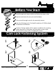
k Quic bly em Ass Ti p Before You Start Read through each step carefully and follow the proper order Separate and count all your parts and hardware Give yourself enough room for the assembly process Have the following tools: Flat Head Screwdriver, #2 Phillips Head Screwdriver and Hammer Caution: If using a power drill or power screwdriver for screwing, please be aware to slow down and stop when screw is tight. Failure to do so may result in stripping the screw.
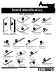
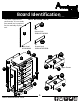
Board Identification Not actual size C B A Left Panel Right Panel 35581340010 35581340020 E Top 35581340030 x4 Support 35581340050 D F Bottom 35581340040 Front Base Rail 35581340060 J I Right Base Rail 35581340090 x5 Drawer Bottom 39991340071310D x2 Front Rail 35581340170 P x4 Drawer Front 35581333140 ameriwoodhome.
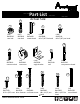
Board Identification Not actual size This piece is paperboard construction. It is not made from wood, but is required for the assembly of your unit. DWR SIDE x10 Drawer Side 39991167346200C T DWR BACK x5 Drawer Back 39991167070350B Back Panel K558100000 K P DWR BACK C T P O S R DWR SIDE Q M DWR SIDE L E J E A P E P Q J DWR SIDE DWR BACK B E K Upper Drawer O I N DWR SIDE D H ameriwoodhome.
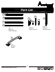
Part List Actual Size 2 3 1 5 4 (x25) #A22620 cam lock (x25) #A22610 cam bolt (x8) #A21660 wood dowel (x50) #A11080 #6 x 7/16" flat head (x60) #A12120 #8 x 7/16" pan head 10 7 6 9 8 (x4) #A22910 connector bolt (x4) #A22920 connector (x10) #A53600 angle bracket (x5) #A21520 compression dowel (x36) #A21110 nail 14 12 15 13 17 11 (x4) (x10) (x30) #A23030 #A17250 #A21970 8‐32 x 5/8" truss drive fastener confirmat screw ameriwoodhome.
Part List 18a Left Cabinet Member 19c 18b 19a 20 Right Cabinet Member 19d 19b 18c Left Drawer Member 18d Right Drawer Member (x5) #A56750 #A84050 safety bracket kit drawer slide pkg. 21 (x5) #A50875 handle ameriwoodhome.
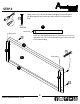
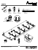
STEP 1 15 Using screws (15), attach the front vertical molding (J) and rear vertical molding (K) to the left panel (A). Please be sure to screw into the surface of the front vertical molding with the pilot holes. Do not fully tighten the screws until next step is completed. (x8) #A12950 finished edge Pilot hole in front vertical molding. J 15 15 15 A 15 15 15 K 15 ameriwoodhome.
STEP 2 Using screws (15), attach the side moldings (P) to the left panel (A). Now tighten the screws that were left lose in the previous step. 15 (x4) #A12950 P front end front end Note: The side molding (P) has an extra hole in it. This is a reference hole. This is to indicate that this is the front end of the side molding. 15 J P 15 front end A K P 15 ameriwoodhome.
STEP 3 2 1 4 marked with a "L" 18a (x2) #A22620 (x4) #A22610 (x15) #A11080 (x5) #A56750 Quick Assembly Tip Proper orientation of CAM LOCK 18a 2 18a 2 18a 2 A 18a 1 18a 4 J 2 18a 1 ameriwoodhome.
STEP 4 Using screws (15), attach the front vertical molding (J) and rear vertical molding (K) to the right panel (B). Please be sure to screw into the surface of the front vertical molding with the pilot holes. Do not fully tighten the screws until next step is completed. 15 (x8) #A12950 Pilot hole in front vertical molding. finished edge J 15 15 B 15 15 15 15 15 ameriwoodhome.
STEP 5 Using screws (15), attach the side moldings (P) to the right panel (B). Now tighten the screws that were left lose in the previous step. 15 P (x4) #A12950 front end Note: The side molding (P) has an extra hole in it. This is a reference hole. This is to indicate that this is the front end of the side molding. front end 15 J 15 P front end B K P 15 ameriwoodhome.
STEP 6 1 (x2) #A22620 2 4 (x4) #A22610 marked with a "R" (x15) #A11080 18b (x5) #A56750 Quick Assembly Tip Proper orientation of CAM LOCK 18b 2 18b 2 18b B 2 18b 4 1 18b 18b J 2 1 ameriwoodhome.
STEP 7 14 Insert four long wood dowels (17) into the larger holes in the top (C). Press the two upper side moldings (R) onto the wood dowels (17) and press until seated onto the top (C). Fasten to the top (C) with screws (14) as shown. Position the upper front molding (S) as shown and attach with screws (14) as shown. 17 (x10) #A13020 (x4) #A21550 14 Be sure to use the holes shown. 14 flat edge 14 R 17 flat edge 14 R 14 C 14 14 S finished edge 17 ameriwoodhome.
STEP 8 19a 8 5 2 (x4) #A22610 (x6) #A12120 (x3) #A53600 19b #A84050 safety bracket kit 2 5 8 5 2 Q C S 2 Do not tighten this screw. 2 19b 19a side view ameriwoodhome.
STEP 9 3 1 Quick Assembly Tip (x8) #A22620 (x8) #A21660 Proper orientation of CAM LOCK 1 1 E x4 3 ameriwoodhome.
STEP 10 7 1 (x4) #A22620 Quick Assembly 2 Tip (x4) #A22920 (x4) #A22610 Proper orientation of CAM LOCK 2 7 7 2 2 7 I H 1 1 You will need to tap the connector (7) with a hammer to fully insert. Be sure the connector is positioned as shown before tapping into hole. ameriwoodhome.
STEP 11 Quick 8 5 1 (x2) #A12120 (x4) #A22620 (x2) #A53600 Tip Proper orientation of CAM LOCK 1 5 8 1 G ameriwoodhome.
STEP 12 2 (x4) #A22610 8 5 (x2) #A12120 (x2) #A53600 5 2 finished edge 8 2 F ameriwoodhome.
STEP 13 6 6 (x4) #A22910 Be sure to use holes closest to the edge. 6 D raw surface 6 6 finished edge ameriwoodhome.
STEP 14 Press the right base rail (I) onto the bottom (D) so the connectors (7) engage the connector bolts (6). Turn the screw in the connector clockwise to lock in place. 7 Turn screw clockwise to lock in place. I D finished edge ameriwoodhome.
STEP 15 UNLOCK Attached the back base rail (G) to the right base rail (I) as shown. I G D ameriwoodhome.
STEP 16 5 (x2) #A12120 UNLOCK LOCK Press the left base rail (H) onto the back base rail (G) as shown making sure the connectors (7) in the left base rail (H) engage the connector bolts (6) in the bottom (D). Securely fasten the cam locks (1) and connectors (7). Attach the back base rail (G) to the bottom (D) using two screws (5). 7 Turn screw clockwise to lock in place. 5 G D ameriwoodhome.
STEP 17 5 UNLOCK (x2) #A12120 LOCK Secure the front base rail (F) to the left and right base rails (H&I) as shown then secure to the bottom (D) with two screws (5). 5 F I D H ameriwoodhome.
STEP 18 13 (x2) #A23030 J A F 13 D 13 ameriwoodhome.
STEP 19 UNLOCK finished edge A E E E E ameriwoodhome.
STEP 20 13 (x2) #A23030 J B E E E E 13 D 13 ameriwoodhome.
STEP 21 UNLOCK Q R B C R A ameriwoodhome.
STEP 22 IMPORTANT! THE BACK PANEL IS A STRUCTURAL PART OF THIS UNIT AND MUST BE INSTALLED PROPERLY. 9 (x36) #A21110 With the help of another person, carefully turn your unit over on its front side as shown. Position the back panel as shown making sure bottom edge is flush with the edge of the bottom and side edges are aligned squarely with the left and right panels. Nail straight into the back edge of the left and right panels, top and bottom as shown.
STEP 23 Carefully stand the unit upright. Attach three angle brackets (8) to a front rail (Q) as shown. Position the front rail (Q) onto the bottom (D) and secure with three screws (5). 8 5 (x6) #A12120 (x3) #A53600 5 Q 5 8 5 5 5 Q Q ameriwoodhome.
STEP 24 2 (x5) #A22610 5 20 (x20) #A12120 (x10) #A54520 You will start the drawer assembly in this step. All 5 drawers assemble the same way. The only difference is the upper drawer front (M) is shorter in height. 5 5 20 5 x1 N x4 M 20 5 x5 2 ameriwoodhome.
STEP 25 5 (x20) #A12120 Attach drawer sides to all five drawer fronts (M&N) as shown using screws (5). Be sure the grooves in the drawer sides are centered with the groove in the drawer fronts. DWR SIDE 5 5 DWR SIDE x1 N x4 M x5 5 5 ameriwoodhome.
STEP 26 Quick Assembly 10 Tip 1 (x5) #A22620 (x5) #A21520 Insert a cam lock (1) and compression dowel (10) into all five drawer braces (L). Attach a drawer brace (L) to each drawer front as shown. Proper orientation of CAM LOCK UNLOCK 1 L x5 10 DWR SIDE L DWR SIDE x1 N x4 M ameriwoodhome.
STEP 27 DWR SIDE raw surface O L DWR SIDE x1 N x4 M ameriwoodhome.
STEP 28 12 Attach a drawer back to the drawer sides and drawer brace as shown. You will need a hammer to lightly tap the drive fasteners (12). 12 (x30) #A21970 12 12 DWR SIDE DWR BACK L 12 12 DWR SIDE x5 N M ameriwoodhome.
STEP 29 11 18c 21 left drawer side 4 18d right drawer side (x20) #A11080 (x5) #A50875 (x5) #A56750 (x10) #A17250 marked with a "R" 4 Attached the slides first and then the handle. DWR SIDE marked with a "L" 11 4 DWR SIDE 11 M N x5 18c 21 ameriwoodhome.
STEP 30 19c 19d (x1) #A84050 For Masonry, Concrete, or other wall materials: Consult your local hardware store for appropriate anchors to securely attach the safety bracket. IMPORTANT: THIS UNIT MUST BE SECURE TO THE WALL TO HELP PREVENT TIPOVER. FOLLOW THESE INSTRUCTIONS TO INSTALL THE ANTI‐TIPPING SAFETY BRACKET PROVIDED WITH THIS PRODUCT. WARNING Serious or fatal crushing injuries can hole occur from furniture tipover.
STEP 31 Note: The drawer bracket holes are slotted. Drawer fronts can be adjusted by loosening screws, making needed adjustments and retightening screws. Note: Drawer with shorter drawer front (M), goes in the top drawer position. M N N N cabinet member roller N drawer runner roller ameriwoodhome.
Maximum Loads This unit has been designed to support the maximum loads shown. Exceeding these load limits could cause sagging, instability, product collapse, and/or serious injury. 50 lbs 22.6 kg 35 lbs 15.8 kg (each drawer) Warning: Risk of injury to persons ‐ do not place a television on this furniture. This furniture is not approved for use with a television. Certificate of Conformity 1. This certificate applies to the Dorel Home Furnishings, Inc. product identified by this instruction manual. 2.
Register your product to receive the following: * New trend details ‐ sneak peek on what's new * Surveys ‐ have a voice within our community * Exclusive deals and discount codes * Quick and easy replacement part service To register your product, visit ameriwoodhome.
Español Cubierta Delantera Este libro de instrucciones contiene información IMPORTANTE de seguridad. Por favor lea y manténgalo para referencia en el futuro. No Regrese este producto! Comuniquese con nuestro amistoso equipo de servicio al cliente para obtener ayuda. Llamenos al: 1‐800‐489‐3351 (Gratis) Lunes ‐ Viernes 9am ‐ 5pm CST Visitar: www.ameriwoodhome.com PRECAUCION Este mueble puede volcarse y causar graves heridas y/o muerte. Anclar el mueble a un poste de madera en la pared (si esto se requiere).
Español Página 8 Fije la moldura vertical delantera (J) y la moldura vertical trasera (K) en el panel izquierdo (A) con los tornillos (15). Asegúrese de atornillar en la superficie de la moldura vertical delantera con los agujeros guía. Página 9 Fije las molduras laterales (P) en el panel izquierdo (A) con los tornillos (15). Nota: la moldura lateral (P) tiene un agujero adicional. Este es un agujero de referencia. Esto es para indicar que este es el frente de la moldura lateral.
Español Página 21 Presione el riel de la base derecha (I) en la parte inferior (D) para que los conectores (7) enganchen los pernos del conector (6). Gire el tornillo en el conector en el sentido de las manecillas del reloj para fijarlo en su lugar. Gire el tornillo en el sentido de las manecillas del reloj para fijarlo en su lugar. Página 22 Fije el riel de la base trasera (G) al riel de la base derecha (I) como se muestra en la figura.
Español Página 31 Comenzará el ensamblaje del cajón en este paso. Los cinco cajones se ensamblan de la misma manera. La única diferencia es que el frente del cajón superior (M) es más corto en altura. Página 32 Fije los lados del cajón a los cinco frentes de los cajones (M y N) como se muestra en la figura con los tornillos (5). Asegúrese de que las ranuras en los lados del cajón estén centradas con la ranura en los frentes del cajón.
Español OPCIÓN 1: acoplado a un travesaño de la pared (método recomendado) Ubica un travesaño en la pared utilizando un localizador de travesaños. Coloca tu unidad contra la pared, con el soporte de seguridad alineado en ese lugar. Para facilitar la entrada del tornillo, puedes perforar un agujero guía de 1/8" (3 mm) de diámetro a través del soporte de seguridad hasta llegar al travesaño. Introduce el tornillo en el travesaño de la pared a través del soporte de seguridad.
Français Couverture Avant CE LIVRET D'INSTRUCTION CONTIENT DES INFORMATIONS IMPORTANTES SUR LA SÉCURITÉ. VEUILLEZ LIRE ET GARDER POUR UNE RÉFÉRENCE FUTURE Ne retournez pas ce produit! Contactez notre équipe de service à la clientèle amicale d'abord pour obtenir de l'aide. Appelez‐nous: 1‐800‐489‐3351 (sans frais) du Lundi au Vendredi de 9h à 17h Heure Centrale Visitez: www.ameriwoodhome.com ATTENTION Le meuble peut basculer et causer des blessures graves ou la mort.
Français Page 8 À l'aide des vis (15), attachez la moulure verticale avant (J) et la moulure verticale arrière (K) au panneau de gauche (A). Veuillez s'assurer de visser dans la surface du moulure vertical avant avec les trous pilotes. Page 9 Attachez les moulures latérales (P) au panneau de gauche (A) à l'aide des vis (15). Remarque : La moulure latérale (P) comporte un trou supplémentaire. C'est un trou de référence. C'est pour indiquer que c'est l'extrémité avant de la moulure latérale.
Français Page 21 Appuyez sur le rail de base droit (I) dans le fond (D) de sorte que les connecteurs (7) s'engagent dans les boulons de connecteur (6). Tournez la vis dans le connecteur dans le sens des aiguilles d'une montre pour verrouiller en place. Tournez la vis dans le sens des aiguilles d'une montre pour la verrouiller. Page 22 Fixez le rail de base arrière (G) au rail de base droit (I) comme indiqué.
Français Page 31 Vous allez démarrer l'assemblage du tiroir dans cette étape. Tous les 5 tiroirs s'assemblent de la même manière. La seule différence est que l'avant du tiroir supérieur (M) est plus court. Page 32 Fixez les côtés du tiroir sur les cinq faces du tiroir (M et N) comme indiqué à l'aide des vis (5). Assurez‐vous que les rainures dans les côtés du tiroir sont centrées avec la rainure dans les façades des tiroirs.
Français OPTION 1 : ancrage sur un colombage (méthode privilégiée) Localisez un colombage dans le mur à l'aide d'un détecteur de colombage. Placez votre meuble contre le mur en maintenant le support de sécurité aligné au meme endroit. Pour faciliter l'insertion de la vis, il est recommandé de percer un trou d'essai de 1/8 "de diamètre (3 mm) à travers le support de sécurité dans le colombage. Passer la vis à travers le support de sécurité pour l'insérer dans le colombage.