
Manual

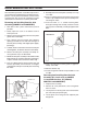


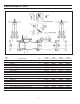


AIR GAP DRAIN INSTALLATION
REAR VIEW SIDE VIEW
AIR GAP DRAIN
APPLICATION
The Air Gap Drain is designed to be installed under the
relief valve on Ames RP and RPDA devices to catch minor
relief valve discharges created by pressure uctuations of
the supply line. The Ames Air Gap Drain is approved by
the USCFCCCHR.
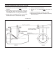
INSTALLATION INSTRUCTIONS
A. Before installation, check with local authorities as an air
gap drain is not approved for all installations.
B. Remove lower two relief valve mounting bolts.
C. Align bolt holes on air gap drain with holes in relief
valve ange.
D. Insert the two bolts which were removed in Step B
through air gap drain and relief valve ange, then tighten.
Price List, Product Series or Design are subject to change without notice.
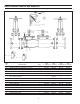
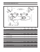
PARTS DIFFERENTIAL PRESSURE RELIEF VALVE FOR SERIES 4000RP
NOTE: Same relief valve is used for all size mainline valves 4" through 10" (100-250mm)
ITEM PART
NO. DESCRIPTION QTY. #
1 Complete 1 7011283
2 Mounting Seat Gasket 1 7011295
3 Stainless Steel Seat Tube 1 7011290
4 Mounting Bolt (not shown) 4 7014619
5 Diaphragm 1 7011292
6 Diaphragm Top Plate 1 7011291
7 Diaphragm Bottom Plate 1 7011294
8 Spring 1 A300887
9 O-ring 1 7011233
10 Repair Kit (#2, #5, #9) 1 7013955
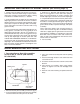
NOTE: The Ames Differential Pressure Relief Valve (relief valve) is designed to open and discharge if the rst mainline
check is fouled; accordingly if the relief valve is discharging the rst service procedure is to examine the rst check
for fouling. The Ames relief valve requires minimal service requirements.
RELIEF VALVE (Section View)
IOM-A-BPA 0904 EDP#7016815 ©Ames Fire & Waterworks 2009
www.amesfirewater.com
A Division of Watts Water Technologies, Inc. USA: Backflow- 1427 N. Market Blvd • Suite #9 • Sacramento, CA 95834 • T: 916-928-0123 • F: 916-928-9333
Control Valves- 18550 Hansen Road • Houston, TX 77075 • T: 713-943-0688 • F: 713-944-9445
Canada: 5435 North Service Rd. • Burlington, ONT. L7L 5H7• T: 905-332-4090 • F: 905-332-7068