
Owner's manual

1
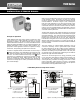
1500 Induction Control Relays
1500 Series
INSTALLATION & SERVICE MANUAL
Principle of Operation
A B/W fl oatless liquid level control system consists of a relay
of the proper type, a holder designed to support one or more
electrodes or probes in the liquid container, and the corrosion
resistant electrodes themselves. In as much as all B/W induction
relays are quite similar differing only in contact arrangement, the
following description of how a 1500-C Relay functions on a
pump down control application will serve to explain the design,
construction, and operating principles for the entire line.
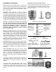
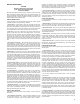
As shown in diagrams below, the laminated core of the relay is
shaped. The primary coil is assembled to the upper bar of the
core, and the secondary coil for the electrode is placed on the
lower bar. An armature located below the legs of the
core is
connected to an insulated arm carrying the movable contacts.
When the armature is raised, these contacts close or open
the motor and electrode circuits, depending upon whether the
contacts are normally open or closed. (Contacts shown normally
open in this example).
When a source of alternating current is connected to the primary
coil at terminals 3 and 4, the primary coil sets up a magnetic
fl ux which circulates through the shortest path following the lines
of least resistance. As shown in Figure 1, this is through the
lower bar of the laminated core on which the secondary coil is
mounted. This magnetic fl ux induces a voltage in the secondary
or electrode circuit coil. No current can fl ow in this coil, however,
until the circuit is completed between the electrodes. Thus, the
electrode circuit voltage being generated within the relay has no
connection with the power line.
The B/W 1500 induction relay utilizes the liquid as an electrical
conductor to complete the secondary circuit between the upper
and lower electrodes. Thus, when the liquid contacts the upper
electrode, the resulting fl ow of current in this circuit sets up a
bucking action in the lower bar of the core. This action tends
to divert lines of magnetic force to the core legs and sets up an
attraction that pulls the armature in to contact with the legs, as
shown in Figure 2. This armature movement closes the electrode
and load contacts.
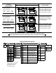
The lower contacts on 1500-C Relays (terminals 9 and 10)
connect the secondary circuit to ground when liquid contacts
the upper electrode and act as a holding circuit to maintain the
relay in its closed position until the liquid falls below the lower
electrode. This holding circuit provides control of the relay over
any desired range in the liquid level, depending on the distance
between the upper and lower electrodes.
The fl ow of current through the low energy secondary circuit
is very small and varies with the voltage of the secondary coil.
The secondary coil is selected to operate over the resistance
of the liquid being controlled. Accordingly, since there is a wide
range of secondary coils from which to choose, it is important
that complete information regarding the nature of the liquid be
furnished when ordering B/W induction relays.
3
5
7
9
8
10
6
4
FLUX
ARMATURE
3
5
7
9
8
10
6
4
FLUX
ARMATURE
PUMP START
ELECTRODE
PUMP STOP
ELECTRODE
A
.C. LINE
TO MOTOR STARTER
A GOOD DEPENDABLE
GROUND RETURN
CONNECTION TO THE
LIQUID IS REQUIRED
GROUND:
Figure 1 - Secondary coil circuit open; armature down. Figure 2 - Secondary coil circuit closed; armature up.
PUMP START
ELECTRODE
TO MOTOR STARTER
A GOOD DEPENDABLE
GROUND RETURN
CONNECTION TO THE
LIQUID IS REQUIRED
GROUND:
A.C. LINE
PUMP STOP
ELECTRODE
1500C Relay Used for Pump Down Control