
User Manual

21
1080 N. Crooks Road • Clawson, MI 48017 • 800.635.0289 • 248.435.0700 • Fax 248.435.8120 • www.ametekapt.com
AUTOMATION & PROCESS
TECHNOLOGIES
952
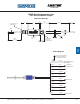
Note 1:Onunsupportedstrokelengthsgreaterthan
4feet,rodsupportbracket(s)andaspecialmagnet
shouldbeused.
Note 2:Specifymagnetasseparatelineitem
(standardmagnetisSD0400800).
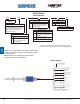
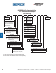
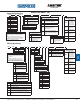
Wiring Diagram
BLUE
WHITE
GRAY
PURPLE
BLACK
RED
-INTERROGATION
+GATE
+INTERROGATION
-15 VDC FOR BIPOLAR
POWER SUPPLY
+15 TO +26 VDC
BROWN
-GATE
PIN-OUT FOR STANDARD
CIRCULAR CONNECTOR
AT TRANSDUCER HEAD
GREEN
ORANGE
YELLOW
NO CONNECTION
NO CONNECTION
NO CONNECTION
POWER SUPPLY
COMMON
PIN-C
PIN-B
PIN-J
PIN-K
PIN-A
PIN-F
PIN-E
PIN-D
PIN-G
PIN-H
POWER SUPPLY*
* FOR UNIPOLAR POWER SUPPLY, IT IS RECOMMENDED
TO CONNECT THIS WIRE TO POWER SUPPLY COMMON
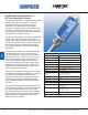
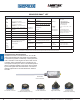
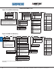
Part Numbering
952CP 0120
Stroke Length
Insert stroke length to 0.1 inch. Enter as
a four-place number. Example: A 12.0”
stroke enters as 0120. To convert metric
strokes, multiply millimeter value by
0.03937 for inch value.
EXX
Null Zone
X
Standard 2 inches.
N_
Insert non-standard Null Zone over
2 inches. (Add non-standard portion
of Null length to stroke length to
calculate list price)
Connector Option
E
Environmental MS connector*
C_
Potted pigtail cable assembly, insert
pigtail length in feet. Example: C6 = 6
foot cable.
Dead Band
X
Standard 2.5 inches.
D_
Insert non-standard Dead Band over
2.5 inches. (add non-standard portion
of Dead Band length to stroke length
to calculate list price)
*IfoptionE(environmentalconnector)isselected,mating
connectorand/orcableassemblymustbeorderedseparately.
Control Pulse
BlueOx
952CP BlueOx