
User Manual


49
1080 N. Crooks Road • Clawson, MI 48017 • 800.635.0289 • 248.435.0700 • Fax 248.435.8120 • www.ametekapt.com
AUTOMATION & PROCESS
TECHNOLOGIES
955
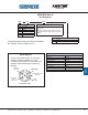
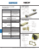
Accessories for 955CA
Item Part Number
Top Mounting Foot (2 min. required) SD0522000
End Mounting Feet - Set includes 2 pieces SD0530600
Side Mounting Feet - Set includes 4 pieces SD0559200
6 Ft. Cable, Straight Connector 949019L6
12 Ft. Cable, Straight Connector 949019L12
6 Ft. Cable, Right Angle Connector 949020L6
12 Ft. Cable, Right Angle Connector 949020L12
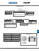
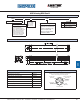
Wiring Diagram
ConnectorView
Use Euro Connector (micro 12 mm single keyway) cordsets,
available from most connector manufacturers or purchased from
Ametek. Install according to the following diagram:
3
2
4
1
Power 13.5 to 30 VDC
(brown wire)
Output
(black wire)
Power Supply
Common
(blue wire)
Program Input
(white wire)
5
Analog Output
Common
(grey wire)
955CA
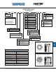
V0
S
0120 X
955CA Analog BRIK Gen III Output Type
V0 = 0 to 10 VDC
V1 = 10 to 0 VDC
C4 = 4 to 20 mA
C2 = 20 to 4 mA
Part Numbering
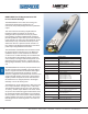
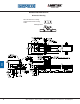
Dimension Drawing
955CA Analog BRIK Gen III
Options
X
No options
E
Wet environment, electronics
sealed to IP68 rating
Stroke Length
Insert stroke to 0.1” as a four-place
number, enter 12.0” stroke as 0120.
OR
Insert stroke in millimeters to 1mm.
Enter as a four-place number
followed by ‘M’. Example: 305mm
stroke entered as 0305M.
Cylinder Magnet Polarity
S = South Pole facing LDT - Typical
N = North Pole facing LDT
Note: It is important to identify the
polarity of the magnet installed in the
cylinder. Most Pneumatic cylinder
manufactures typically install the
magnet with the South Pole facing
out, but we have experienced both
North and South Pole magnets.