Series 1995B Gemco ® Micro-Set Programmable Limit Switch Installation & Programming Manual
1080 North Crooks Road Clawson, MI 48017-1097 Phone: (248) 435-0700 FAX: (248) 435-8120 Internet: www.ametekapt.com www.ametek.com Preface This manual is for the Installation and Maintenance of the Gemco Series 1995B Micro-Set Programmable Limit Switch. Copyright 2000 by AMETEK All Rights Reserved - Made in the U.S.A. Version 0.1 AMETEK has checked the accuracy of this manual at the time it was printed. Any comments you may have for the improvement of this manual are welcomed.
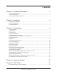
Contents Chapter 1: Introduction/Description 1 Chapter 2: Installation 3 Chapter 3: Programming 5 1.1 Programmable Features ....................................................................................................... 1 1.2 General Information ............................................................................................................. 1 1.3 Controller Features and Functions ........................................................................................ 2 2.
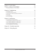
Chapter 6: Security Inputs 23 Chapter 7: Remote Circular Display 24 Chapter 8: Troubleshooting 25 7.1 POS/RPM On Remote Circular Display ............................................................................. 24 8.1 Preliminary Checks ............................................................................................................ 25 8.2 Transducer Excitation Voltages ........................................................................................... 25 8.
Chapter 1: Introduction/Description Chapter 1: Introduction/Description The 1995B Micro-Set is a fully self-contained, single-turn resolver-based programmable limit switch. It includes a three-digit LED display, five output relays, and one fault check relay, and it is fully programmable for the following features: 1.1: Programmable Features Scale Factor There is one scale factor only, permanently set to 360. Electronic Offset Fully programmable offset to any number with the scale factor.
Chapter 1: Introduction/Description It offers an on line fault check which provides an automatic, in-process mechanism to verify that all major programmable limit switch functions are operating properly. The fault check output can be energized by activating the fault check enable input. The output is a mechanical relay with 1 N.O. and 1 N.C. contact, which remains energized during normal operation.
Chapter 2: Installation Chapter 2: Installation This section describes the installation and wiring of a standard 1995B Micro-Set PLS. Changes to these instructions should be made as necessary if special options and/or equipment are used. The 1995B Micro-Set should be installed in an area free of water spray, corrosive gases, flying chips or other foreign matter. The operating temperature should be between 32 and 125 degrees Fahrenheit, with less than 95% relative humidity. 2.
Chapter 2: Installation (B) Combination mechanical cam/resolver systems. Intended as bolt-in replacements to existing switches. The cam/resolver combination unit should be coupled where the existing limit switch is located. Wire and adjust the mechanical cams in accordance with the original press manufacturers specifications and wire the resolver cable to the controller. 2.
Chapter 3: Programming Chapter 3: Programming 3.1: Security Input The security input is often referred to as the Run/Program input. This input is located on the 16-place terminal strip and is discussed in Chapter 4: Expansion Modules. This input prevents unauthorized changes to the programmed functions. With the unit in the Program mode, all functions of the controller can be programmed.
Chapter 3: Programming 3.5: Selecting Number of Outputs Selection of the number of outputs should be done after the system is initialized and , and before any other programming is done. See Chapter 4: Expansion Modules. A) To program the number of outputs desired, the unit must be in the Program mode, then depress . The unit will then show the number of circuits previCIR# - 1 - 7 - 7 - ENT ously stored.
Chapter 3: Programming Where: A = = = = = 5 for 5 outputs 6 for 11 outputs 7 for 17 outputs 8 for 23 outputs 9 for 29 outputs Setpoints are in whole numbers (drop decimal). Example: S.P. = 12 outputs relays with 10 programs: 1467 10 x 6 -2 = 24.45 - 2 = 22 Setpoints/Program The following table shows the relationship between the number of outputs, the number of programs, and the number of setpoints per program. The table only shows a few of the many combinations that are possible.
Chapter 3: Programming C) CIR# - 7 - 7 - 2 - ENT will display the total number of setpoints available for use in the currently selected active program. D) To display the active program, depress CIR# - 7 - 7 - 1 - ENT . To change programs, with the unit in the Program mode, depress (0 thru Highest Program Number) - ENT . NOTE: Program 0 is the first program. If 10 programs were previously selected using Code 770, there will be programs 0-9. 3.
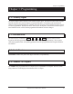
Chapter 3: Programming on a scale factor corresponding to the 360-degree rotation of the resolver. Example: In the foregoing example, with a 360 scale factor, a dwell on of 0 and a dwell off of 100 would look like this: 0 100 359 The shaded area represents the area where the selected limit output relay is energized. Programmable limit switch outputs offer a unique function which normal rotating cam limits cannot, namely, the ability to turn a limit on or off more than once in a 360-degree cycle.
Chapter 3: Programming 3.9: Clear an Existing Setpoint A) Unit must be in the Program mode. B) Depress CIR# - (Output to be Cleared) - ENT . C) Depress CIR ON D) Depress the CLR SET key. Upon depression of the CLR SET the display after Step C is deleted. E) This keypad sequence must be completed once to clear an ON setpoint and a second time to clear the OFF setpoint. See Section 3.8: Setpoints or CIR OFF key until setpoint to be cleared is on the display. key, the setpoint on 3.
Chapter 3: Programming 17 Outputs = 207 Setpoints Available 23 Outputs = 181 Setpoints Available 29 Outputs = 161 Setpoints Available Refer to the Section 3.5: Selecting Number of Outputs. 3.12: Electronic Offset The offset key is used to synchronize the digital display with the actual machine position. The Series 1995B PLS has full scale factor offset capabilities, and the offset is held in nonvolatile memory.
Chapter 3: Programming 3.14: Power-Up in a Position or RPM The 1995B can power up displaying either Position or RPM data. The power-up mode is programmed by entering the following: A) Unit must be in the Program mode. B) Depress CIR# - 1 - 6 - 3 - ENT - (0 or 1) - ENT . If a zero (0) is entered, positional data will be displayed upon power-up; if a one (1) is entered, the unit will power up displaying RPM. 3.
Chapter 3: Programming 3.16: Enable/Disable Outputs During setup, the outputs may be enabled or disabled. When outputs are selected to be disabled, the status LEDs and the relays will be OFF. The unit must be in the Program mode to disable the outputs; as soon as the unit is switched to the Run mode, the outputs will be enabled. The enable/disable feature is programmed as follows: A) Unit must be in the Program mode. B) Depress CIR# - (380 or 381) - ENT . CIR# 380 Enables the Outputs.
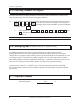
Chapter 3: Programming The graph above shows an example of five steps of linear offset in which the output circuits remain the same in the first step, then are being advanced in the next two steps, retarded between the third and fourth, and remaining unchanged between the fourth and fifth. The first step (501) is programmed so that the outputs will not be affected until after 20 RPM. Then the second step (502) is programmed to linearly advance the selected outputs by 20 degrees between 20 and 60 RPM.
Chapter 3: Programming 3.18: Programming 1995 PLS for Linear Speed A) Unit must be in the Program mode. B) Select the number of circuits that will be offset based on RPM. The affected circuits will always start with CIR# 1 and will follow in ascending sequence to the number specified. Depress: CIR# - 80 - ENT - (1 thru 5) - ENT . NOTE: LS5 cannot be programmed for Linear Speed if it is set for Motion detect. See Section 3.
Chapter 3: Programming 3.20: Time-Based Outputs (Available Only on Option P Units) In instances where it is desirable to have an output actuate based on crank position and turn off based on time, we offer time-based limits. Examples of areas where time-based limits are applicable include lubricators and air blow-off limits. Even if the press stopped in the limit dwell area, it would only stay energized for a specific time period, eliminating potential waste.
Chapter 3: Programming 3.21: Brake Monitor Operational Description The 1995B Brake Monitor PLS offers an on-line monitor which checks the stopping time of the press against a customer selected preset stopping time in milliseconds, and can be used to check the stopping distance at any point during the stroke. With keypad commands, the digital readout will display the stopping time (CIR #174) or the stopping distance (degrees) (CIR# 175) of each cycle.
Chapter 3: Programming PROGRAMMING AND MONITORING To monitor press stopping time, depress CIR# - 174 - ENT. Stopping time will be displayed in milliseconds from 001 to 999. Three decimal points indicate a stopping time in milliseconds, a single decimal point, two places to the left, will indicate a stopping time in seconds to one hundredth of a second. If the customers preset stopping time is exceeded, the display and decimal(s) will flash.
Chapter 3: Programming Programming the Maximum Stopping Time A) Unit must be in the Program mode. B) Depress CIR# - 1 - 7 - 3 - ENT - Maximum Stopping Time - ENT This sets the maximum allowable stopping time in .001 second intervals. If the time required to stop following the loss of the brake monitor contact exceeds the brake monitor stopping time, then the error output LS6 is de-energized. Display of Stopping Time A) Depress CIR# - 1 - 7 - 4 - ENT .
Chapter 4: Expansion Modules Chapter 4: Expansion Modules The 1995B PLS provides five outputs. A 1995E Expansion Module is required for each additional six outputs desired, up to a total of 29 outputs, or four expansion modules (units with Remote Circular Displays may use only up to 23 outputs total, or three expansion modules). The circuit location of each expansion module is defined by the location of a two-pin jumper on an eight-pin block in the upper left corner of the module.
Chapter 5: Fault Check Chapter 5: Fault Check The Fault Check option provides an automatic in-process self-diagnostic mechanism to verify that all PLS functions are operating properly. The Fault Check option will detect and disable system operation in the event of any of the following problems: 1. Disconnect or severed resolver cable. 2. Open or shorted resolver signals. 3. Resolver excitation failure. 4. Resolver-to-digital converter or associated electronic failure. 5.
Chapter 5: Fault Check 5.
Chapter 6: Security Inputs Chapter 6: Security Inputs The Run/Program security inputs may be operated by an isolated contact, current sourcing, or a current sinking device, 5V DC @ 10mA. See Fig 11-2, Chapter 11: Wiring Diagrams. NOTE: The 1995 PLS cannot be programmed until the security input has been enabled by means of connections from Pin 9 (+5V DC) to Pin 10 (Security +) input and from Pin 11 (Security -) input to Pin 14 (GND).
Chapter 7: Remote Circular Display Chapter 7: Remote Circular Display The Remote Circular Display (1995-1446) is ideal for mechanical stamping presses and shears. Either position or RPM can be displayed on the large 3/4 LED digital display. A 360° bar graph will increment in 10° intervals showing the angle of the resolver. The remote circular display gets its RS422 synchronous signal from the four-place terminal strip located on the back of the 1995 programmer.
Chapter 8: Troubleshooting Chapter 8: Troubleshooting The following procedures are intended to aid in isolating system malfunctions to field replaceable modules. These modules include the 1995 programmer, output relays, remote circular display, transducer, and all interconnecting cables. Once isolated, the defective module should be replaced and returned to the factory for repair. NOTE: Field repair beyond this level is not recommended. 8.
Chapter 8: Troubleshooting 8.3: Electrical Noise and Power Quality Consideration The 1995 PLS is designed for use in an industrial environment and incorporates extensive transient suppression circuitry. However, the same general installation rules should be followed that apply to all microprocessor-based equipment.
Chapter 8: Troubleshooting If the resolver cable must be run through a terminal strip, it must be mounted in a small enclosure with no other wiring. The shields of the incoming and outgoing cable must be tied together and isolated from ground. Special purpose contact inputs all operate by connecting the input pin on the 1995 PLS to a power or GND terminal (depending on method wired per Fig. 11-2; Chapter 11: Wiring Diagrams) on the 1995 PLS through a remote contact or solid-state switch.
Chapter 9: Specifications Chapter 9: Specifications 9.1: 1995 Micro-Set PLS Programmer Resolution Scale Factor Scan Time Temperature Range Operating Voltage -12 Bit (4096) -360 -Standard 335 µseconds -32°F to 125°F (Operating) -0°F to 150°F (Storage) -110/120V AC 50/60 Hz 300 mA INPUTS Transducer -Resolver accurate to ±3 arc minutes provides resolution of 1 part in 4096, 2800 RPM maximum speed. Logic -Fault check and security 5V DC at 10mA.
Chapter 9: Specifications 9.4: DC Solid-State (Single Pole, Normally Open) Maximum Load Load Voltage Range Leakage Current On State Voltage Drop Surge Current Min. Operational Current Operate Time Reset Time -2 Amp DC -5 to 60V DC -2 mA Maximum -1.5V Maximum -5A (1 Sec. Maximum) -50 mA -0.5ms Maximum -2 ms Maximum 9.5: 1995E Output Expansion Module Operating Voltage Temperature Range Outputs -110/120V AC 50/60 Hz 100 mA -32°F to 125°F (Operating) 0°F to 150°F (Storage) -Same as Programmer 9.
Chapter 10: Troubleshooting Guide Chapter 10: Troubleshooting Guide SYM PTOM POSSIBLE CAUSES Display Shows: EEE Incorrect programming sequence or unit is not in the program mode. Review Chapter 6: Security Inputs for Run/Program information. Display Shows: EE0 EE1 EE2 EE3 EE4 Unit has detected a fault. Review Chapters 5: Fault Check and 8: Troubleshooting. Display Shows: PPP Loss of initialization. Loss of initialization indicates a severe power fluctuation or electrical noise.
Chapter 10: Troubleshooting Guide SYM PTOM POSSIBLE CAUSES System operates properly but exhibits a random momentary loss of all outputs. Random momentary loss of all power to the system. A loss of power for as short a duration as 50 milliseconds will cause the system to shut down. When power is reapplied, the system can take several seconds to reinitialize itself. During this time period, all outputs are disabled.
Chapter 10: Troubleshooting Guide SYM PTOM Brake Monitor Fault POSSIBLE CAUSES The maximum allowable stopping time has been exceeded (CIR # 173). Review Section 3.21: Brake Monitor O perational Description. If the brake fault output trips and the maximum allowable stopping time has not been exceeded, either the Micro- Set detected 5 RPM of movement without sensing the brake input, or the brake input relay module (SD0395100) has failed. Refer to Section 3.21: Brake Monitor O perational Description.
Chapter 11: Wiring Diagrams Chapter 11: Wiring Diagrams Fig 11-1 Wiring Diagram Drawing E0177100 Installation and Maintenance Manual 33
Chapter 11: Wiring Diagrams Fig 11-2 Wiring Diagram Drawing E0198203 34 Installation and Maintenance Manual
Chapter 11: Wiring Diagrams Fig 11-3 Wiring Diagram Drawing E0204400 Installation and Maintenance Manual 35
1080 N. Crooks Road l Clawson, MI 48017 800-635-0289 l 248-435-0700 l Fax 248-435-8120 www.ametekapt.com l www.ametek.com 898 01/03.