
Manual


9
Installation and Maintenance Manual
Chapter 3: Programming
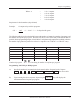
on a scale factor corresponding to the 360-degree rotation of the resolver. Example: In the foregoing
example, with a 360 scale factor, a dwell on of 0 and a dwell off of 100 would look like this:
0
100 359
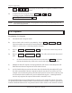
0 20 80 100 180 200 270 359
The shaded area represents the area where the selected limit output relay is energized. Programmable
limit switch outputs offer a unique function which normal rotating cam limits cannot, namely, the ability to
turn a limit on or off more than once in a 360-degree cycle. Multiple dwells allow several dwell on
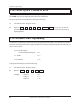
and dwell off values to be programmed for a particular limit. Example: Dwell on settings of 20,
100, 200, and dwell off settings of 80, 180, 270 would look like the following:
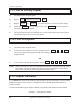
Another feature of programmable limits is the ability of programming a dwell on or a dwell off only.
If only a dwell on setting is programmed, the output will activate at the dwell on setting and remain
on to 359 degrees. Example: Dwell on setting of 180 and dwell off not programmed will result in
the following:
0 180
359
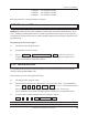
Conversely, if only a dwell off setting is programmed, the output will activate from 0 degrees to the
dwell off setting. Example: Dwell on not programmed, dwell off set at 180 degrees will result in
the following:
0 180 359
The programmable limits also have the ability to shift the dwells to turn on sooner. This can be done
to compensate for mechanical lag in the devices they are controlling as the machine speed increases.
(See Section 3.17: Linear Speed Offset for more details). Limits can also be programmed to turn off
based on timed settings.