
Manual


13
Installation and Maintenance Manual
Chapter 3: Programming
3.16: Enable/Disable Outputs
During setup, the outputs may be enabled or disabled. When outputs are selected to be disabled, the
status LEDs and the relays will be OFF. The unit must be in the Program mode to disable the outputs;
as soon as the unit is switched to the Run mode, the outputs will be enabled.
The enable/disable feature is programmed as follows:
A) Unit must be in the Program mode.
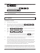
B) Depress
CIR# 380 Enables the Outputs.
CIR# 381 Disables the Outputs.
CIR#
(380 or 381)
-
ENT
-
.
NOTE: If you try to disable the outputs in the Run mode, the unit will display EEE.
3.17: Linear Speed Offset (Available Only on Option P Units)
This feature allows limit switch outputs, one through five, to be programmed to automatically advance
and retard as machine velocity varies. The number of circuits affected by speed offset, the amount of
offset, and the RPM range over which the offset develops are all keypad programmable. The amount
to offset per RPM change will be the same for all outputs selected for this type of operation. This
feature is used to compensate for the mechanical lag in machine controls.
The 16-step linear speed offset feature allows up to 16 different offset steps to be selected and a
different amount of positive or negative (advance or retard) offset to be programmed between each of
the sixteen steps.
Access Codes 501 through 516 are used to select the successive steps that define a ramp between the
various offset values. That is, Code 501 is used to access and program the ramp between 0 RPM and
the RPM value assigned to the first step; Code 502 is used to access and program the ramp between
the RPM value of the first step and the RPM value assigned to the second step; and so on.
After using the access code to call up a step for programming, the CIR ON key is depressed, followed
by the total amount of offset (from zero offset) to be applied to the circuit at the specified RPM value.
The CIR OFF key is depressed next, followed by the RPM value of that step. The programmed offset
value will be the total amount of offset being applied to the circuits from their zero offset starting values.
This allows the circuits to be advanced or retarded between any two steps. See Section 3.18:
Programming 1995 PLS for Linear Speed.