
Manual


Chapter 3: Programming
Installation and Maintenance Manual
14
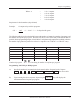
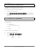
The graph above shows an example of five steps of linear offset in which the output circuits remain the
same in the first step, then are being advanced in the next two steps, retarded between the third and
fourth, and remaining unchanged between the fourth and fifth. The first step (501) is programmed so that
the outputs will not be affected until after 20 RPM. Then the second step (502) is programmed to linearly
advance the selected outputs by 20 degrees between 20 and 60 RPM. Circuits originally programmed to
turn on at 150 degrees and off at 350 degrees will be turning on at 130 degrees and off at 330 degrees
while at 60 RPM. The third step (503) is programmed to advance these same outputs to a total of 50
degrees as RPM rises between 60 and 100 RPM. The example circuit mentioned above that was origi-
nally programmed to turn on at 150 degrees and off at 350 degrees will now be turning on at 100 degrees
and off at 300 degrees while at 100 RPM. The fourth step (504) is programmed to retard the circuits
back to a total of 30 degrees as RPM continues to rise from 100 to 140 RPM. The example circuit,
originally programmed to turn on at 150 degrees and off at 350 degrees is now turning on at 120 degrees
and off at 320 degrees while running at 140 RPM. The fifth step (505) is programmed to maintain a fixed
30 degrees of total offset between 140 and 200 RPM.
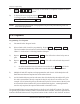
0 150 350 359
1ST COMPENSATION AT 20 RPM
2ND COMPENSATION AT 60 RPM
0 130 330 359
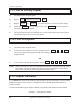
3RD COMPENSATION AT 100 RPM
4TH COMPENSATION AT 140 RPM
0 120 320 359
The offset (advance or retard) is applied linearly between each step, and the offset follows the same
curve as RPM decreases. Example: At 80 RPM, offset value would be 35°.
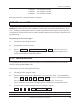
0 150 350 359
0 100 300 359
5TH COMPENSATION AT 200 RPM
0 120 320 359
NORMAL PLS DWELL