
Manual


17
Installation and Maintenance Manual
Chapter 3: Programming
3.21: Brake Monitor Operational Description
The 1995B Brake Monitor PLS offers an on-line monitor which checks the stopping time of the press
against a customer selected preset stopping time in milliseconds, and can be used to check the stopping
distance at any point during the stroke.
With keypad commands, the digital readout will display the stopping time (CIR #174) or the stopping
distance (degrees) (CIR# 175) of each cycle. If the time from deenergization of the press clutch voltage
to stopping the ram exceeds a customers programmed value, the brake monitor output relay will de-
energize which can be used to stop further press operation. This output can be reset by momentarily
opening and then closing the fault check input. Please note that the brake monitor system operates
independently of the fault check system but both use the fault check input to reset their individual faults.
Opening the fault check input will de-energize the fault and brake monitor output relays allowing the user
to verify that these outputs are operating properly and have not been hardwired.
NOTE: In efforts to make the brake monitor fail-safe , we have changed the brake monitor circuit so
that if you see motion without seeing the brake input, a break fault will occur.
WIRING
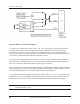
Wire the programmer per Fig 11-2 (Chapter 11: Wiring Diagrams). In this drawing, relay LS6 is the
brake monitor relay. It is normally energized (N.O. contact is closed and N.C. contact is open) and de-
energized on a fault condition. Operating in this manner a disconnected wire or disconnected relay will
indicate a fault condition.
Relay LS5 is either a standard LS output or the motion detect output, as selected by the customer. If
operating as a motion detect output, the relay will energize when the transducer speed is greater than the
customer programmed RPM value.
The brake monitor calculates stopping time by monitoring the time span between the clutch disengage-
ment and the presss coming to a complete stop. The system begins this timing sequence when it sees
the isolated contact, wired between input terminals 14 and 15, open. This isolated contact can be the
contact of an existing relay in your control circuit or it can be provided by the Gemcos optional Brake
Monitor input Relay #SD0395100 as shown on the next page. The contact of the brake monitor input
relay must be open when the clutch disengages, and all wiring between its isolated contact and terminals
14 and 15 of the 1995 programmer must be protected from induced electrical noise.