
Manual


Chapter 4: Expansion Modules
Installation and Maintenance Manual
20
Chapter 4: Expansion Modules
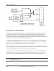
The 1995B PLS provides five outputs. A 1995E Expansion Module is required for each additional six
outputs desired, up to a total of 29 outputs, or four expansion modules (units with Remote Circular
Displays may use only up to 23 outputs total, or three expansion modules). The circuit location of
each expansion module is defined by the location of a two-pin jumper on an eight-pin block in the upper
left corner of the module. This jumper must be installed for the expansion module to operate. Two
pairs of pins, located in the lower right corner of the expansion module, should be jumpered on only the
last module in the wiring group. However, if a Remote Circular Display is being used, do not install
these jumpers. Remove both jumpers from all intermediate expansion modules. See Chapter 11:
Wiring Diagrams, Fig. 11-3 for additional expansion module wiring information. Each expansion module
is provided with a full set of terminal strip designation decals. To avoid confusion, the appropriate
decals should be installed along the output terminals, based on the location of the output selection
jumper outlined below.
Fig. 4-1
See Section 3.5: Selecting Number of Outputs, for instructions on how to program unit for use with
expansion modules.