
Manual


23
Installation and Maintenance Manual
Chapter 6: Security Inputs
Chapter 6: Security Inputs
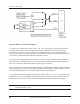
The Run/Program security inputs may be operated by an isolated contact, current sourcing, or a current
sinking device, 5V DC @ 10mA. See Fig 11-2, Chapter 11: Wiring Diagrams.
NOTE: The 1995 PLS cannot be programmed until the security input has been enabled by means of
connections from Pin 9 (+5V DC) to Pin 10 (Security +) input and from Pin 11 (Security -)
input to Pin 14 (GND).
NOTE: If the Run/Security program is not needed (always in the Program mode) install jumper wires
form Pin 9 (+5V DC) to Pin 10 (Security +) and from Pin 11 (Security -) to Pin 14 (GND)
on the 16-place resolver connector.