
Manual


25
Installation and Maintenance Manual
Chapter 8: Troubleshooting
Chapter 8: Troubleshooting
NOTE: Field repair beyond this level is not recommended.
8.1: Preliminary Checks
Check all system wiring connections at the transducer and at the programmer. Amphenol-type connec-
tors on the transducer and its cabling should be checked for tightness. A slight tug on all wire termina-
tions should verify a good connection. Push-on cable connectors should be checked for proper con-
nections. Verify that incoming AC voltage to the 1995 PLS is between 105V AC and 125V AC.
The following procedures are intended to aid in isolating system malfunctions to field replaceable
modules. These modules include the 1995 programmer, output relays, remote circular display, trans-
ducer, and all interconnecting cables. Once isolated, the defective module should be replaced and
returned to the factory for repair.
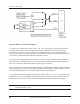
8.2: Transducer Excitation Voltages
AC voltage across terminals 2 (RH) and 3 (RL) of the 16-place terminal strip (labeled Red and BK/R)
should be from 1.6 to 1.9V RMS. This is the output voltage being supplied to the resolver rotor. If this
voltage is not present, disconnect the resolver wires at the 1995 programmer and recheck the voltage.
If this voltage is still not present, the resolver excitation circuitry in the 1995 programmer has failed and
should be replaced. If this voltage appears, a shorted condition in the resolver or its cable should be
checked.
The return signals from the resolver stator windings are wired to the 1995 programmers 16-place
terminal strip at terminals 4 and 5 (labeled White and BK/W), and terminals 6 and 7 (labeled Green and
BK/G). To verity the presence of these AC return signals, put a voltmeter across terminals 4 and 5 and
rotate the resolver. A voltage reading that rises and falls (0-2.3V RMS) between these terminals as the
resolver is rotated indicates a good resolver return signal. Repeat this same procedure with your meter
across terminals 6 and 7. No voltage or a voltage that does not vary as the resolver rotates indicates an
open or shorted condition in the resolver windings or the resolver cable.
To check for an open or shorted condition inside of the resolver, disconnect the Amphenol-style con-
nector from the transducer and make the following checks at the resolver: Measure the resistance
across Pins A & B (rotor); it should measure approximately 19-50 ohms. Then measure across Pins C
& D (stator); it should measure approximately 50-120 ohms. The resistance across E & F should be
the same as C & D.
NOTE: Due to the many different types of resolvers that we have used over the years, these
resistance readings are only approximate and are intended for locating opens or shorts in the
resolver wires or windings.