
Manual

Chapter 1: Introduction/Description
Installation and Maintenance Manual
2
It offers an on line fault check which provides an automatic, in-process mechanism to verify that all
major programmable limit switch functions are operating properly. The fault check output can be
energized by activating the fault check enable input. The output is a mechanical relay with 1 N.O. and 1
N.C. contact, which remains energized during normal operation. A programmable motion detect
output will energize a relay when the transducer speed meets or exceeds the customer-preprogrammed
RPM value.
Also offered is an on-line brake monitor that checks the stopping time of the machine against a customer
selected preset stopping time in milliseconds, and which can be used to check the stopping distance at
any point in the stroke. A dedicated output remains energized when the stop time parameters are within
tolerance. An excessive stop time will cause the relay to de-energize, which could be used to stop
further machine operation.
SOFTWARE OPTION P ENHANCES THE SYSTEM BY OFFERING:
n Multiple Programs - Allow storage of job setups for future use. This saves time
spent reprogramming and lessens the chance of programming errors when tooling is
changed.
n Speed-Induced Offsets - On many variable speed machines, the limit switch outputs
have to be adjusted when the speed increases or decreases. This option automatically
adjusts specified circuits based on speed.
n Time-Based Outputs - Specified outputs can be programmed to turn on based on
position and turn off based on time (0.01 - 9.99 seconds).
1.3: Controller Features and Functions
The controller is housed in an all metal case that can be panel mounted. The controller consists of a
keypad, a CPU Board, and a Power Supply I/O Board.
The following features are found on the 1995B Micro-Set.
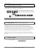
n Display A (3) three-digit LED readout and a 10-place bar graph are provided.
The LED readout displays current angular position and/or RPM and
programming details, while the bar graph shows fault check, program
status, and limit status.
n I/O Mechanical relays, AC solid-state, and DC solid-state relays are
available, and any combination can be specified. The example in the
catalog shows three AC and three DC solid-state relays being speci-
fied. There is a fixed price adder for any combination of relays other
than all mechanical (6M). The fault check relay will always be a
mechanical relay regardless of the type of output relays specified.
See Chapter 9: Specifications.
NOTE: The Bar graph will not display expansion board relay status.