Series 2110 ® GEMCO Shut Height Monitor Shut Height Monitor with Resolver/LDT Interface Installation and Programming Manual T13692 Cover Working.
1080 North Crooks Road Clawson, MI 48017-1097 Phone: (248) 435-0700 FAX: (248) 435-8120 Internet: www.ametekapt.com www.ametek.com Preface This manual is divided into three parts. Part 1 provides an introduction and installation instructions for Series 2110 Shut Height Monitor. Part 2 contains instructions for the basic operation and programming of the monitor. Part 3 contains four appendixes: Error Messages, Function Summary Chart, Catalog Numbering System, and Specifications.
Contents Chapter 1: Theory of Operation ..........................................................................1 Chapter 2: Hardware Overview 2.1: Standard Modules ........................................................................................................... 2 Controller (FMMP01) ..................................................................................................... 3 Relay Output (FMOR01) .........................................................................................
Adjust the Turns Counting Factor ..................................................................................23 4.2: LDT Configuration Function ..........................................................................................24 Wire Speed (300) ...........................................................................................................24 Count Direction (301) ....................................................................................................
Chapter 1: Theory of Operation Chapter 1: Theory of Operation The Series 2110 shut height monitor accurately indicates shut height positions to quickly and accurately assist setup personnel in changing a die on a mechanical stamping press. Positions can be monitored within a thousandth of an inch. During a die change, the monitor displays the position of the press’s shut height on a large LED display. If the shut height is moved beyond its programmed end limits, the monitor de-energizes a limit switch.
Chapter 2: Hardware Overview Chapter 2: Hardware Overview The shut height monitor contains a heavy-duty case which can hold up to five modules: n Power Supply n Controller (CPU) n Digital Output (optional) n Analog Output (optional) n Resolver Input (optional) n Linear Displacement Transducer L1 (optional) n Linear Displacement Transducer V1 (optional) n Relay Output (optional) The shut height monitor’s faceplate contains a 6-digit, seven-segment LED display and four programming keys.
Chapter 2: Hardware Overview 2.1: Standard Modules This section provides descriptions of the shut height monitor’s standard modules. See also Section 2.2: Input Modules. For wiring instructions, see Section 3.2: Mounting & Wiring. Controller (FMMP01) This module contains the Central Processing Unit (CPU) which is used to process data it receives from the resolver or LDT (depending on which input device is used). It then shows the position of the shut height on the monitor’s display.
Chapter 2: Hardware Overview This module also provides two input pins for use as a field configured latch or synchronized handshake input. The latch input freezes the digital output data while the PLC reads it. The data is updated when the input is released. When configured for synchronized handshake, the PLC must provide a clocked square wave input into these input pins.
Chapter 2: Hardware Overview Variable Pulse (FMIP01) Input Option V1 This module is used with an LDT that provides its output in the form of a pulse width modulated RS-422 signal. The module only works with Gemco 951VP2110 LDT’s. LDT Input (FMIP02) Input Option L1 This module will accept an output from a controlled pulse, start stop pulse or variable pulse magnetostructive LDT. This card accepts a wide range of LDT inputs and faster updates than the variable pulse described above.
Chapter 2: Hardware Overview PROGRAM The program LED turns on when the controller is in program mode and turns off when the controller is not in program mode. Functions cannot be programmed when this LED is off. FAULT The fault check OK LED turns on when the power supply’s fault check relay is closed, indicating the system is OK. This LED will turn off when a fault is detected, indicating that the fault check relay is open. OK MVT FLT The movement fault LED turns on when a movement fault is detected.
Chapter 2: Hardware Overview (F) The function key is used to begin a process for programming a function. When this key is pressed, the monitor prepares itself for the entry of a specific function number. ↑ The scroll key is used to scroll through the monitor’s list of function numbers, as well as other lists. This key is also used to increment selected digits shown on the monitor’s LED display.
Chapter 3: Mounting and Wiring Chapter 3: Mounting and Wiring This chapter provides instructions for mounting and wiring the shut height monitor. These instructions have been divided into two sections: Section 3.1: Mounting and Section 3.2: Wiring.
Chapter 3: Mounting and Wiring 5. Insert each #6-32 UNC screw into each of the monitor’s screw holes. 6. Using a 7/64" Allen wrench, secure the screws into position. This will secure the mounting rails. Eight to 10 inch pounds of torque is required. Resolver The resolver is mounted and coupled to the main ram adjust drive motor, or another shaft that rotates when the shut height is adjusted. NOTE: Backlash and slop in the shaft will affect shut height accuracy.
Chapter 3: Mounting and Wiring Figure 3-1 Dimensional Drawing 10 T13692 chapter 3.
Chapter 3: Mounting and Wiring Figure 3-2 Transducer Mounting Figure 3-2A Universal Mounting Kit Figure 3-2B Termination Kit Installation and Programming Manual T13692 chapter 3.
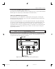
Chapter 3: Mounting and Wiring 3.2: Wiring This section contains pinout diagrams for each module. System wiring diagrams follow. Controller Module (FMMP01) The controller has two connectors: a D9 connector (J1) for RS-232 and RS-485 serial communications, and a program lockout connector (J2) intended for a keyswitch. (See Figure 3-3). Making connections to both connectors is optional. However, the program lockout connector must be jumpered to allow the unit to enter program mode.
Chapter 3: Mounting and Wiring Figure 3-4 Relay Output Pinout Diagram Power Supply Module (FMPS01) The power supply module has a main power input, an auxiliary input, and a fault check output. (See Figure 3-5). Power input: 85-265 VAC at 450 mA maximum. Fault check output: 8 amps 250 VAC, 30 VDC, 1/4 HP 125, 250 VAC. It is recommended that the fault check contacts be connected to the required safety interlock for the press. Auxiliary input: 85-265 VAC at 12 mA maximum.
Chapter 3: Mounting and Wiring Resolver Module (FMIR01) The resolver module has an eight-position connector. (See Figure 3-6). The terminal wire size for all positions is No. 22-12 AWG. Terminal 7 and 8 are not used. Figure 3-6 Resolver Pinout Diagram Variable Pulse LDT Module (FMIP01) Input Option V1 The variable pulse LDT module has an eight-position connector. It is only necessary to connect your LDT to positions 1 through 4. (See Figure 3-7). Positions 1 and 2 provide +24 VDC to power the LDT.
Chapter 3: Mounting and Wiring LDT Input (FMIP02) Input Option L1 This module will accept an output from a controlled pulse, start stop pulse or variable pulse magnetostrictive LDT. (See Figure 3-7). This card accepts a wide range of LDT inputs and provides faster updates than the variable pulse module as described on page 14. The pulse width signal is converted to position data which the monitor displays. The module also provides +24 VDC to supply power to the LDT.
Chapter 3: Mounting and Wiring Figure 3-9 Digital Output Wiring Diagram Drawing E0232200 16 T13692 chapter 3.
Chapter 3: Mounting and Wiring Figure 3-10 Digital Output Wiring Diagram Drawing E0232200 Installation and Programming Manual T13692 chapter 3.
Chapter 3: Mounting and Wiring Analog Output (FMOA01) Output Option A1 The Analog Output board provides two channels of analog output that can be independently configured and scaled. Each channel can be configured for an output based upon position or velocity. Velocity will be RPM if the sensor is a resolver or inches/mm per second if the input sensor is an LDT.
Chapter 3: Mounting and Wiring Fig 3-12 Wiring Diagram Analog Output Drawing E8005090 Installation and Programming Manual T13692 chapter 3.
Chapter 3: Mounting and Wiring 20 T13692 chapter 3.
Chapter 3: Mounting and Wiring Fig 3-14 LDT - Based System Wiring Diagram Drawing E0228700 Installation and Programming Manual T13692 chapter 3.
Chapter 3: Mounting and Wiring Fig 3-15 Wiring Monitor to Cable Termination Kit Drawing 22 T13692 chapter 3.
Chapter 4: Programming Chapter 4: Programming This chapter provides detailed descriptions and instructions for programming all shut height monitor’s functions. A complete list of functions (with brief explanations) can be found in Appendix B: Function Summary Chart. This chapter divides the functions up into the following seven sections. 4.1 Resolver Configuration Functions 4.2 LDT Configuration Functions 4.3 Monitor Setup Functions 4.4 Press Setup Functions 4.5 Digital Outputs 4.
Chapter 4: Programming Figure 4-1 calls out the shut height monitor’s programming keys. Following this figure are descriptions of these keys and how they work, as well as, a short tutorial on how to use the keys. Status LEDs PROGRAM¹ FLT¹¹¹OK¹ MVT¹FLT¹ BOLSTER BED UPR¹LIM ¹ LWR¹LIM ¹ INCH MM AUX SERIES 2110 F( ) Enter Key Shift Key Scroll Key Function Key Figure 4-1 Programming Keys Programming Keys Defined The shut height monitor has four keys located on the front panel.
Chapter 4: Programming The shift key is used to move to a specific digit shown on the monitor’s LED display. This can be done to either select a function number or a value for a function. To move to a specific digit on the display, select the function key and then the shift key. The right-most digit will then flash. This indicates that the digit is activated to be incremented. (To increment the digit, select the scroll key.) Continue to select the shift key until the desired digit is activated.
Chapter 4: Programming Turns Counting (301) The Turns Counting function defines the number of revolutions the resolver must rotate before the scale factor is reached. For example, when this function is set at 2 and the scale factor is set at 100, the resolver will have to make two full revolutions before 100 counts is reached. The Turns Counting Function can be disabled by setting its value to 0.
Chapter 4: Programming NOTE: The shut height monitor is defaulted to stay in program mode for 120 seconds. The monitor will drop out of program mode if a key is not pressed within this time. If this occurs, you will have to repeat steps 1-3. Further, the access code (2100) is provided initially. This code can be changed through the use of the New Access Code function. For security reasons, this function can only be implemented when the monitor is in supervisory mode.
Chapter 4: Programming NOTE: The shut height monitor is defaulted to display position in inches. It can be changed to read position in millimeters, however. To make this change, see Unit of Measurement in Section 4.3: Monitor Setup Functions. Steps 11-13 will have to be repeated if the unit of measurement is changed. Set the Position Offset to 0 (F) 11. Select the function key. The monitor displays “F-----”. 302 8 Enter 000000 8 Follow steps 14-16 12. Select function number 302.
Chapter 4: Programming Adjust the Turns Counting Factor (F) 20. Select the function key. 301 The monitor displays “F-----”. 21. Select function number 301 (Turns Counting function). Select the enter key. 8 Enter 001000 8 The monitor displays “001000”. 22. Enter 001000. Select the enter key. 23. Select the function key. The monitor displays “F-----”. (F) 24. Select function number 302 (Position Offset function). Select the enter key.
Chapter 4: Programming Option V1 - This module can only be used with Gemco LDTs with a part number starting with 951VP1992 or 951VP2110. Wire speed and recirculations for these LDTs have been configured at the factory for maximum resolution. 4.2 NOTE: Always refer to the LDT legend plate for programming wire speed (Function 300). The wire speed will always be between 500.000 and 600.000 micro sec./inch. Option L1 - This module is designed to be used with any LDT with digital output.
Chapter 4: Programming Count Direction (301) The Count Direction function is used to change the direction the shut height position will move as the LDT’s magnet travels along the guide rail. A 0 value will cause the position to increment as the magnet moves away from the LDT head. A value of 1 will cause the position to increment as the magnet moves toward the LDT head. The default for this function is 1. For further explanations, see Figure 4-2.
Chapter 4: Programming Position Offset (302) NOTE: Make sure the unit of measurement function is selected to your desired units before entering the value for the Position Offset function. The unit of measurement is set in inches at the factory. For instructions on selecting the unit of measurement, see Unit of Measurement in Section 4.3: Monitor Setup Functions. The Position Offset function is used to synchronize the monitors displayed value with actual shut height. This value can range from -99.
Chapter 4: Programming Fault Pulse Time (306) The Fault Pulse Time function is used to program the pulse time of the fault signal sent by the LDT when it detects an error. When the monitor receives a fault signal of this pulse time, it will indicate an error (see Appendix A: Error Messages). The default for this function is 10 microseconds. This value can range from 1 to 99 microseconds. A 0 is entered in this function to disable it.
Chapter 4: Programming 8 3. Enter a 0 to disable this function or enter a new output type. Select the enter key. *If used, program Function 308. Consult the factory for settings. 4.3: Monitor Setup Functions This section provides descriptions and instructions for the shut height monitor setup functions. These functions provide the means to customize the monitor’s setup for a specific installation. Before any of these functions can be programmed, the monitor must be in program mode.
Chapter 4: Programming Decimal Location (13) The Decimal Location function is used to program the resolution of the shut height and all position data shown on the monitor’s LED display. Resolution can be either displayed in whole units, tenths, hundredths, or thousandths. Resolution choices correspond to the following values: 0 = whole unit; 1 = tenths; 2 = hundredths; and 3 = thousandths. To change the resolution shown on the monitor’s LED display, perform the following steps: (F) 1.
Chapter 4: Programming (F) 4. The default value for the Move Detection Time-Out function is 5.00 seconds. To change this value for the position hold dwell time, select the function key. 12 The monitor displays “F-----” 8 5. Enter function number 12. Select the enter key. Enter new dwell value 8 The monitor displays the current value for the position hold dwell time. This value is in seconds. 6. Select the new dwell time. Select the enter key.
Chapter 4: Programming 4.4: Press Setup Functions This section provides descriptions and instructions for press setup functions. These functions provide the means to customize the press’s setup for a specific installation. Before these functions can be programmed, the monitor must be in program mode. To put the monitor in program mode, see Program Mode Access in Section 4.6: Program and Supervisory Mode Functions.
Chapter 4: Programming NOTE: The power supply’s auxiliary input must be wired properly in order for the Move Detection Time-Out function to work. For instructions on wiring the auxiliary input, see Section 3.2: Wiring. Bolster Offset (303) The Bolster Offset function is used to program the thickness of a bolster plate installed on the bed of the press. The value programmed in this function is internally subtracted from the programmed shut height.
Chapter 4: Programming Enter new setting 3. Enter the new value. Select the enter key. 8 4.4: Relay Setup Functions - Option K1 If your system includes the optional relay module (K1), the following function numbers are used for setup. Before these functions can be programmed, the monitor must be in program mode. To put the monitor in program mode, see Program Mode Access in Section 4.7: Program and Supervisory Mode Functions. The following is a list of the press setup functions.
Chapter 4: Programming Lower End Limit (401) The Lower End Limit function is used to program the lower end limit of the shut height opening. This can prevent the ram from accidentally exceeding its mechanical adjustment capabilities. If the shut height reaches or goes below the value programmed in this function, the lower limit relay will de-energize and the lower limit LED will turn on. This can cause power to be taken away from the press’s ram adjust motor(s) if the lower limit relay is properly wired.
Chapter 4: Programming Relay Override (403) The Relay Override function is used to temporarily allow the press operator to readjust the shut height once it has exceeded a programmed end limit. If the upper or lower limit relays are wired into the power interlock system, power may be lost when the shut height goes beyond the values programmed in the upper or lower limit functions. (For more information, see Upper End Limit and Lower End Limit.
Chapter 4: Programming Latch/Synchronize Handshake (201) The function defines which of the two methods will be used to stabilize position data while the PLC reads. The two options are Latch or Synchronize Handshake. Synchronize Handshake tells the digital board to update on the transitional edge of a clocked square wave input (pin 24). Latch tells the digital board to update continuously until the latch input pin is activated by driving high, then the outputs will freeze.
Chapter 4: Programming Error Condition Output State (203) This function allows you to select how the digital outputs will react to a failure in the encoder module, transducer and/or cable. The following three options describe what will happen on a failure. (F) 1. Select the function key. The monitor displays “F-----” 203 8 0, 1 or 2 Enter either 2. Enter function 203. Select the enter key. The monitor displays the function’s current value. 3. Enter either 0, 1 or 2.
Chapter 4: Programming 4.6: Analog Outputs The Analog Output board provides two channels of analog output that can be independently configured and scaled. Each channel can be configured for an output based upon position. Each of the two analog output channels generate a simultaneous voltage and current output. You can use either the current or voltage output on one channel but not both.
Chapter 4: Programming C) Scaling Analog Output The analog output is scaled by programming a minimum position value followed by the analog output value required at that position. A maximum position value is then programmed followed by the analog output required at that position. The analog output value specified can be any value within the following allowable range: Voltage Current -10 VDC to 10 VDC 0mA to 20mA The analog output will stop changing upon reaching the minimum and maximum values programmed.
Chapter 4: Programming (F) 8. Select function key. X03 9. Enter function number X03. Select enter key. 8 The monitor displays current maximum positions value. Enter 002000 8 10. Enter 2000. Select enter key. This sets maximum position value at 2000 counts. The monitor displays 002000. (F) 11. Select Function key. The monitor displays “F-----”. 12. Enter function number X06. Select enter key. X06 8 The monitor displays current voltage output value linked to maximum count value. 14. Enter 8.
Chapter 4: Programming - Select maximum position value Function No. X09 - Select analog output value to be linked to maximum position value Function No. X12 4.7: Program and Supervisory Mode Functions This section provides descriptions and instructions for program and supervisory mode functions. These functions are used to put the shut height monitor in either program or supervisory mode, as well as program the length of programming time and change the program mode access code.
Chapter 4: Programming NOTE: If the shut height monitor displays only one zero (i.e. “0”), then the program lockout connector is not jumpered. For wiring instructions, see Section 3.2: Wiring. Enter access code 3. Enter either the program or supervisory mode access code. The default program mode access code is 2100. Select the enter key. 8 The monitor is now in either program mode or supervisory mode. The program mode LED is turned on.
Appendix A: Error Messages Appendix A: Error Messages The shut height monitor displays an error message when an error occurs during machine operation. The format for errors appearing on the monitor’s LED display is illustrated in Figure A-1. Descriptions and solutions for errors are provided in charts A-1 through A-3. Error messages are grouped into the following three categories: System Error This type of error is caused by one of the monitor’s modules or input device.
Appendix A: Error Messages PROGRAM FLT OK MVT FLT BOLSTER BED UPR LIM LWR LIM INCH MM AUX Describes the Type of Error SEr = System Error OEr = Operating Error EEr = Entry Error Indicates Slot that Relates to Error* 1 = Slot 1 2 = Slot 2 3 = Slot 3 4 = Slot 4 Indicates Module that Relates to Error * 0 = Controller 6= 1= 7= 2 = Resolver 8= 3 = LDT (VP) 9= 4 = LDT (CP) A= 5 = Relay Output B= Indicates Error (refer to error chart for descriptions and solutions to errors) * For entry errors, the three right-
Appendix A: Error Messages The following charts contain descriptions and solutions for the three types of errors that can appear on the monitor’s LED display. To clear errors, perform the solutions found in charts A-1, A-2, and A-3, followed by pressing either the scroll, shift, or enter. Error Displayed Error Description SEr101 A configuration error has occurred. SEr102 The monitor's function parameter memory has been corrupted. SEr103 The battery for the monitor's memory is low.
Appendix A: Error Messages Error Displayed Error Description EEr 1 An invalid function number was entered. EEr 2 An invalid system configuration was entered. EEr 3 A value outside the function's acceptable range was entered. EEr 4 An incorrect parameter was entered. EEr 5 A value was programmed into the Lower End Limit function that is greater than the value programmed in the Upper End Limit function.
Appendix A: Error Messages The following errors will cause the upper and lower limit relays to de-energize: Error Displayed SEr320 SEr330 SEr331 OEr101 OEr330 or OEr320 Error Description This is a resolver-specific error. See Chart A-6. The input device is not connected to the monitor's input module. This is a LDT-specific error. See Chart A-7. The press's ram did not move within the time programmed in the Move Detection Time-Out function.
Appendix A: Error Messages Error Conditions (306) If the monitor displays “SEr320” one of four error conditions relating to the resolver has occurred. These conditions include primary open, primary shorted, S1, and S4 open or shorted. To have the monitor display the error condition which has occurred, perform the following steps: (F) 1. Select the function key. 306 ↵ The monitor displays “F-----”. 2. Select function number 306. Select the enter key.
1080 N. Crooks Road • Clawson, MI 48017 • USA 800-635-0289 • 248-435-0700 • Fax 248-435-8120 www.ametekapt.com • www.ametek.com T13692 Cover Working.indd 2 3/17/04, 6:23 AM 1162 2110.M1R2 03/04.