
Instruction Manual

5200 Solid State Relays
5200 Series
INSTALLATION & SERVICE MANUAL
PRINCIPLE OF OPERATION
B/W 5200 Solid State Controls are offered in two basic types for use in a wide
range of low and high sensitivity applications. Both are designed to operate
on either 115 or 230 volts AC at 50/60 hertz. Both incorporate a low voltage
sensing circuit. Both are also capable of performing control functions directly
from electrodes suspended in a well or tank, the B/W Unifl oat level sensing
system, or various pilot devices such as pressure, fl ow and limit switches,
thermostats and pushbuttons, etc.
In addition, their operating characteristics are virtually unaffected by ambient
temperatures ranging from -40°F to +180°F, or by variations from 80% to
110% of their rated voltage. Both controls are also furnished with a complete
set of R1 fi xed sensitivity resistors or a variable resistance potentiometer
to permit adjustment of operation based on the resistance of the liquid or
material to be controlled. See tables below.
5200-LF1 Low Sensitivity Control
The basic components of this control are a transformer, a circuit board with
voltage divider circuit, a silicon controlled rectifi er (SCR), and a load to provide
isolated DPDT contacts. The sensing circuit voltage is 8.0 volts ac.
5200-HF2 High Sensitivity Control
This control is similar to the 5200-LF1, but with two basic differences: First, a
rectifi er is used to convert the sensing circuit voltage from ac to 9.6 volts dc;
second, a fi eld effect transistor (FET) is added to provide higher sensitivity.
This permits positive operation on liquids with very high resistance.
Since the voltage divider circuit compares the liquid resistance to the R1
sensitivity resistor on both 5200-LF1 and 5200-HF2 controls it is important that
the R1 resistor selected be rated higher than the resistance of the liquid or
other sensing circuit.
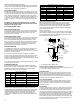
Direct Operation
In direct operation, the load relay is energized when the level sensing
circuit is completed. When operating from electrodes for pump down
operation, and liquid is below lower electrode, a high resistance is sensed
across terminals 13 & 14, and a negative, or out-of-phase, signal is fed to the
SCR.
When liquid rises to touch the upper electrode, a low resistance is sensed
across terminals 13 & 14, and the signal to the SCR becomes positive, or
in-phase, turning the SCR on, which, in turn, energizes the load relay to start
the pump.
When load relay is energized, the holding circuit contact (4-7) closes to hold
in the relay through the lower electrode and the liquid resistance until liquid
level falls below the lower, or pump stop, electrode, at which time the SCR
turns off and de-energizes the load relay to stop the pump.
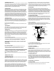
Inverse Operation
In inverse operation, load relay is de-energized when the level sensing circuit
is completed. In this mode of operation, function of load relay is reversed.
When operating from electrodes for pump up operation, and liquid is below
lower electrode, a positive, or in-phase, signal turns the SCR on, energizing
the load relay to start the pump.
When liquid rises to touch the upper electrode, a negative, or out-of-phase,
signal turns the SCR off, de-energizing the load relay and stopping the pump.
The holding circuit contact (1-7) closes, keeping the load relay de-energized
until the liquid again falls below lower electrode.
5200-HF2 High Sensitivity Control
R1 Sensitivity
Resistor
Maximum Lead
Wire Lengths*
Application
Recommondations
10,000 ohms 50,000 feet Ordinary water with medium to highmineral
content, sewage, water soluble oil and starch
solutions, long distance applications
22,000 ohms 50,000 feet Water with low mineral content (soft - not
distilled or demineralized), sugar syrup
solutions, long distance applications.
68,000 ohms 50,000 feet Steam condensate, corn syrup, strong alcohol
solutions up to 50%
330,000 ohms 50,000 feet Alcohol solutions up to 70%
820,000 ohms 35,000 feet Deionized or distilled water, 95% glycerine, 90%
hydrogen peroxide, 95% ethyl alcohol, granular
solids with high moisture content
2.2 megohms 12,000 feet Glacial acetic acid, acetone, granular solids with
some moisture content
5.6 megohms 4,000 feet M.E.K. (Methyl ethyl ketone)
12.0 megohms 2,000 feet Anhydrous ammonia
NOTE: DI water, glycols, alcohols and granular solids may require the 2.2, 5.6
or 12.0 megohms R1 resistor depending upon their purity or moisture content.
5200-LF1 Low Sensitivity Control
R1 Sensitivity
Resistor
Maximum Lead
Wire Lengths*
Application
Recommondations
270 ohms 15,000 feet All metallic circuits, B/W Controls Unifl oat
470 ohms 15,000 feet Strong electrolytes: Plating solutions.
1,000 ohms 15,000 feet Weak eletrolytes: Ammonium hydroxide, borax,
acetic acid
1,800 ohms 11,000 feet Most food processing applications: Beer wine,
fruit juices,milk buttermilk
3,900 ohms 5,000 feet Highly corrosive acid or caustic solutions where
electrode current must be minimized to extend
electrode life: Hydrochloric acid, sulfuric acid,
etc
10,000 ohms 2,000 feet Ordinary water with medium to high mineral
content, sewage, water soluble oil and starch
solutions.
22,000 ohms 900 feet Sugar syrup solutions, most water with low
mineral content. (Soft water-not distilled or
deionized water. Use 5200-HF2 Control)
*Distance shown in the tables above are based upon the use of
two 18-gauge lead wires installed in 1/2” diameter conduit.
Basic Specifi cations
Dual Voltage
Either 115 or 230 volts AC at 50/60 hertz
Contacts
Silver Cadmium Oxide
Contact Ratings
10 amperes at 120 or 240 volts AC or 28 volts DC,
1/4 hp at 120 volts AC. and 1/3 hp at 240 volts AC
Arrangement
Double pole, double throw load contacts plus single pole,
doublethrow holding circuit contacts
Power Required
9 volt-ampere, 6 watt
Operating Temp.
-40°F to 180°F
Low Energy
Sensing Circuit
AC - 8 volts (less than 30 milliamperes) for 5200-L,
DC - 9.6 volts (less than 1 milliampere) for 5200-H