
Instruction Manual

2
INSTALLATION INSTRUCTIONS
These instructions relate primarily to the B/W electrode system of liquid level
sensing. Call 1-800-635-0289 to request the B/W Catalog (Z66) for complete
specifi cations, wiring and electrode equipment, etc.
ELECTRODE LEAD WIRES
Shielded cable is not required. Generally the size of the wire used is passed
upon the physical strength required to meet given installation condition. Size
14 to 18 gauge wire is generally strong enough for private buried or overhead
wiring, although size 26 gauge wire is adequate for positive relay operation.
In some long distance applications, communication cable or telephone circuits
may be used. In all cases, however, control circuit wires must have good
insulation, and splices or connections must be watertight and insulated from
ground.
Special Note - In order to prevent feed-back which can cause faulty
operation, electrode lead wires should not be run in the same conduit
with power or load carrying circuits.
ELECTRODE LEAD WIRE LENGTH
5200-LF1 Low Sensitivity Control
These controls operate with 8 volts ac on the sensing circuit, and in general,
the maximum lead length is determined by the capacitance of the lead wires
and the value of the R1 sensitivity resistor. Refer to Table on page 1 for
suggested maximum lead lengths.
5200-HF2 High Sensitivity Controls
These controls operate with 9.6 volts dc on the sensing circuit, and in general,
the maximum lead length is determined by the resistance of the lead wires.
These controls will operate reliably with electrode lead lengths of several
miles, but it is important to select the correct R1 sensitivity resistor to assure
positive operation over these extreme distances. Refer to Table on page 1
for suggested maximum lead lengths. If your application involves greater
distances than those shown, please contact factory.
GROUND CONNECTIONS
In all installations using electrodes, a good external ground connection and
a dependable return circuit to the liquid are required. In most instances,
grounding to a metal pipe leading to the tank is suitable, but electrical conduit
should not be used for this purpose.
If a good ground connection to the liquid is not available, an additional
ground or common electrode is required. When used, the ground or common
electrode should extend slightly below the longest operating electrode. In
addition, it is also desirable to ground the control chassis directly to the ground
terminal or through a mounting screw.
If PVC well casings or drop pipes are used to contain the electrodes, a ground
or common electrode is required.
R1 SENSITIVITY RESISTORS
Both the high sensitivity and the low sensitivity controls are shipped from
the factory with a complete set of fi xed resistors or with a variable resistance
potentiometer. Variable resistance potentiometers are furnished in three
different ranges according to the table which follows.
To determine which fi xed sensitivity resistor to install, please refer to the
table which follows. When operating from electrodes, select a resistor having
a sensitivity value greater than the specifi c resistance of the material to be
controlled. Any of the resistors can be used when operating from switch
contacts, but the smallest value is recommended. Fixed resistance R1
resistors should be installed as shown on the wiring diagram furnished with
the control.
A - Load Relay Will Not Pull In
1. Power Failure or No Voltage at AC Line Terminals
Voltage at power in-put terminals should be 115 volts ac between terminals 10
& 11 or 230 volts ac between terminals 10 & 12.
2. Defective Control
To check control, disconnect electrode and load connections from control
terminals. Apply line voltage to the appropriate terminals (10-11) or (10-12),
and touch terminals 13 and 14 with an insulated jumper wire. Load relay
should pull in when the jumper is connected, and drop out when the jumper is
removed. Failure to do so indicates a defective control.
3. Poor Ground Connection
Controls will not function unless a good dependable ground connection is
made to terminal 13. If a load relay does not pull in when liquid contacts
the upper electrode, check ground connection to be sure it complies with
installation instructions.
4. Broken Wires
A broken or loose wire from the control to the upper electrode or the ground
(common electrode) will prevent load relay from pulling in. Broken wires can
be checked by shorting the upper electrode to ground, or to the common
electrode if used, at the electrode holder. If relay fails to pull in, one or both of
the electrode leads is open. The individual leads can be checked by running
temporary wires from the control to the electrode holder outside of conduit.
If the load relay now pulls in, when shorting electrodes as noted above, the
break is between the control and electrode holder. If load relay pulls in when
the leads are shorted with a jumper at holder, but not at electrode tips, the
break is in the electrode suspension wire.
SERVICE INSTRUCTIONS
B/W Solid state controls are designed and built to require a minimum of
service in the fi eld. Each one is tested at the factory to insure positive
operation, and should not be altered or tampered with prior to installation.
If a control does not operate properly after it has been installed with the
proper sensitivity resistor added, the following information will be helpful in
determining the probable cause.
Direct Operation
In direct operation, the load relay is energized when the liquid reaches the
upper electrode or Unifl oat reed switch level, and electrode current is fl owing.
Be sure sensitivity resistor has been installed between terminals 14 and 15,
and a good ground connected to terminal 13.
6
6
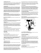
3%2)%3
2%,!9
05-034!243
4!.+
%,%#42/$%
(/,$%2
05-034/03
!#,INE
6OR6
OR(Z
4/05-0
34!24%2
#HASSIS'ROUND
4HROUGH-OUNTING3CREW
'ROUNDRETURNTOTANK
ORELECTRODEIFREQUIRED
3ENSITIVITY
2ESISTOR
,OAD
#ONTACTS
6!2)!",%
2%3)34!.#%
0/4%.4)/-%4%2
/04)/.!,!4
%842!#/34
2
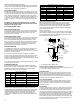
Sensitivity Ranges
Relay Type R1 Resistor Direct Operation Inverse Operation
5200-LF1
Fixed R1
Resistor
Up to 16,000 ohms Up to 26,000 ohms
5200-LV1
Variable
100 to 700 ohms 200 to 1,200 ohms
5200-LV2
Variable
600 to 15,000 ohms 1,000 to 24,000 ohms
5200-HF2
Fixed R1
Resistor
Up to 11.6 megohms Up to 12.0 megohms
5200-HV3
Variable
2,000 to 100,000 ohms 2,000 to 100,000 ohms
5200-HV4
Variable
.007 to 1.0 megohms .007 to 1.0 megohms
5200-HV5
Variable
.047 to 5.0 megohms .047 to 5.0 megohms
Fixed Resistor Sensitivity
5200-LF1 Sensitivity Control 5200-HF2 High Sensitivity Control
Part Number Nominal Resistance Part Number Nominal Resistance
04-154900 270 ohms 04-149400 10,000 ohms
04-155000 470 ohms 04-138400 22,000 ohms
04-138300 1,000 ohms 04-138500 68,000 ohms
04-155100 1,800 ohms 04-138600 330,000 ohms
04-155200 3,900 ohms 04-138800 .007 to 1.0 megohms
04-149400 10,000 ohms 04-138900 820,000 ohms
04-138400 22,000 ohms 04-139000 2.2 megohms
04-139100 5.6 megohms
PUMP DOWN