
Instruction Manual

3
6
6
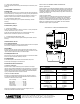
3%2)%3
2%,!9
05-034/03
4!.+
%,%#42/$%
(/,$%2
05-034!243
!#,INE
6OR6
OR(Z
4/05-0
34!24%2
#HASSIS'ROUND
4HROUGH-OUNTING3CREW
'ROUNDRETURNTOTANK
ORELECTRODEIFREQUIRED
3ENSITIVITY
2ESISTOR
,OAD
#ONTACTS
6!2)!",%
2%3)34!.#%
0/4%.4)/-%4%2
/04)/.!,!4
%842!#/34
2
PUMP UP
5. Sensitivity Resistor Too Low
If the sensitivity resistor value is too low for the resistance or conductivity of the liquid
to be controlled, the load relay will not pull in, or it will buzz and chatter before pulling
in. In either case, the sensitivity resistor should be replaced with a higher value
resistor (see table, page 2). If in doubt about R1 resistor selection, furnish factory
with details on liquid, or send sample of liquid for testing.
6. Fouled Electrodes
Accumulation of dirt, oil, grease, or other deposits on the electrodes may insulate
them and prevent load relay from pulling in. If this occurs, the electrodes should be
inspected and cleaned at regular intervals, as required, to eliminate the diffi culty.
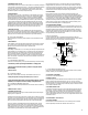
If unusual quantities of oil, grease or sludge are encountered, the electrodes can
be mounted inside a pipe that is fl ushed with clean water. A 4” pipe should be used
-- with the bottom located below the lowest expected water level, and vent holes
provided at the top so that the level inside and outside the pipe will be the same. A
small fl ow of water entering the top of the pipe will cause an outward fl ow of water
from the bottom of the pipe and prevent undesirable material from entering. Thus,
the electrodes have a clear surface on which to operate, and will stay clean.
7. Electrodes Too Short
It is possible for an installation to be completed in which the upper electrode is
suspended at a point where the liquid cannot make contact. All installations should,
of course, be checked to make sure that the proper electrode lengths are provided. If
stand pipes are used, make sure pipe is vented above upper electrode setting.
B - One Level Operation
If control operates at one level only (starts and stops at one electrode level) check
following:
1. Electrode Wires
If wires between control and electrodes are interchanged, load relay will not operate
over a range in level, but from the lower electrode only. To correct, simply reverse
electrode connections either at terminal strip or electrode holder.
2. Holding Circuit
If the holding circuit (terminals 4--7) is not closing, the load relay will operate from the
upper electrode only. If the holding circuit is not opening, the relay will operate from
the lower electrode only. This holding circuit contact can be checked for continuity
with an ohmmeter. If defective, and if contacts 2-5-8 are not being used for load
connections, contacts 5-8 can be used as a holding circuit contact. Move the internal
jumper from terminal 7 to terminal 8, and move the lower electrode connection from
terminal 4 to terminal 5.
C - Intermittent Operation
If the control occasionally short cycles or operates intermittently, check the following:
1. Continuously monitor input voltage for fl uctuations or voltage spikes.
2. Check for physical vibration caused by contactors or magnetic starters
mounted nearby.
3. Check A-4 & A-6.
D - Constant Chatter
If load relay contacts chatter continuously, check defective control as in A-2.
1. If relay now operates correctly, check A-4 & A-6, B; C-1 and C-2.
2. If relay still chatters with terminals 13 & 14 jumpered together, the load relay
is defective, or the capacitor across the load relay coil may be defective.
E - Load Relay Will Not Drop Out
If relay will not drop out when liquid falls below lower electrode, check the following
points:
1. Defective Control - See A-2.
2. Grounded Electrode Leads
A ground in the lead wire to the upper or lower electrode will prevent the relay from
dropping out on low liquid level.
If the distance from the holder to the control is relatively short, the best way to check
for ground is to connect replacement wires from the terminal strip to electrode holder,
outside of conduit, and test for proper operation. If load relay drops out properly, it is
safe to assume that a ground exists in the original wires to the electrode holder.
If control is located a considerable distance from the electrode holder, check for
ground as follows: Disconnect power, remove wires from terminals in electrode
holder, and allow them to stick up in the air to eliminate the possibility of contacting
a grounded part. Then turn on power. If load relay pulls in, a short is indicated in the
upper lead wire to ground between the control and the electrode holder.
If the load relay does not pull in , short the relay with a piece of insulated wire by
bridging between relay terminals 13 & 14. The load relay should pull in when this
connection is broken. If the relay does not drop out, a short to ground is indicated
in the lower electrode lead between the control and electrode holder. If any of these
conditions exist, disconnect the power and replace the grounded wires.
3. Electrode Holder
Excessive dirt or moisture over the insulation at the electrode holder or the
electrodes can cause faulty operation. The interior of the electrode holder and its
underside should be kept clean and dry. Conduit connection should be made so that
no condensation can enter the holder. The underside of vertically mounted holders
should never come in contact with the liquid. Insulated rod electrodes should be
used with horizontally mounted holders. Electrodes should be kept clean and free
of dirt or grease. A periodic check should be made to make sure that they do not
become fouled with fl oating debris or insulating deposits.
4. Length of Electrode Lead Wire
On installations with excessive distance (over 1,000 feet) between a 5200-LF1 low
sensitivity control and the tank, capacitance in the lead wires from the control to the
electrodes may affect normal operation. If wired for direct operation, capacitance
would cause the load relay to hold in when the liquid leaves the lower electrode. If
wired for inverse operation, the load relay would fail to pull in. In this event, a 5200-
HF2 high sensitivity control should be used.
Inverse Operation
In inverse operation, the relay is energized when liquid falls below the lower
electrode, and current ceases to fl ow. Be sure sensitivity resistor has been installed
between terminals 13 & 14, and a ground connected to terminal 15.
F - Load Relay Will Not Pull In
If relay will not pull in when liquid drops below lower electrode, failure to operate is
probably caused by one of the following conditions:
1. Power Failure or No Voltage
See Section A-1 under Direct Operation.
2. Defective Controls
To check the relay, disconnect electrode and load connections from relay terminals.
Apply line voltage to the appropriate terminals, (10 & 11 or 10 & 12), and short
between terminals 14 & 15 with an insulated jumper wire. The load relay should drop
out when the jumper is connected and pull in when the jumper is removed. Failure to
do so indicates a defective control.
3. Grounded Electrode Leads
A ground in the lead wire to the upper or lower electrode will prevent the load relay
from pulling in . Section E-2 describes how to isolate the grounded wire when the
relay is being used for direct operation. This same method can be used when the
control is being used for inverse operation, but the functions must be reversed. (i.e.
“drop out” interchanged with “pull in”). In section E-2, bridge between terminals 14 &
15 instead of 13 & 14.
4. Electrode Holder - See Section E-3
5. Length of Lead Wires
Excessive distance will not allow the 5200-LF1 low sensitivity control to operate
when the liquid drops below the lower electrode. See Section E-4.