
User Manual

B/W Controls
Series 7014
Uni oat
®
Installation Manual
IMPORTANT
Just before nal installation into the tank and with the switches mounted inside the guide tube, slide the oat up and
down the tube. This will reset all the switches to their normal condition. If the Type “C” Reed Switch was ordered,
the common switch wire (C) in the UNIFLOAT is bare and is attached to the ground screw with a green wire.
RATINGS:
The factory assembled units are rated for operating pressures up to 500 PSI and temperatures of 0° to 250° F
(-19° to 121°C). For pressure tight applications pipe sealing compound should be used on the holder mounting
threads. It is best to install in an upright position, but can be mounted up to 30° from vertical. While some small
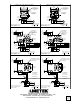
loads such as pilot lights may be operated directly from the switches, most applications will require control relays.
Conventional relays can be used, however, B/W relays have unique characteristics that make them desirable for
many applications. Diagrams are attached showing B/W recommended wiring for various relays in some typical
applications.
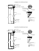
SWITCH ADJUSTMENT:
Refer to your order for details on the switch settings provided when the UNIFLOAT was shipped from the factory.
If different settings are desired, remove cover on holder. Do not remove any other ttings. Remove the internal
assembly consisting of the switches and common wire, (On Type “C” Reed Switch Only), terminal block, and
mounting plate. The set lengths for each switch actuation is measured from the bottom of the terminal block
mounting plate, and is 1.25” + longer than the set length measured from the bottom of the holder mounting threads,
based on a liquid with 1.0 speci c gravity. Each switch is marked with the actuation point, and the differential travel
is 0.1 inch. Switch actuation will depend on the actual speci c gravity of the liquid. See the tables below for set
length adjustments for liquids with speci c gravities other that 1.0.
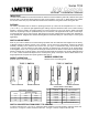
DIRECT OPERATION:
Switches close on the rising level.
FLOAT MAGNET
FLOAT MAGNE
T�
FLOAT MAGNET
FLOAT MAGNET
FLOAT MAGNE
T�
FLOAT MAGNE
T�
FLOAT MAGNE
T�
FLOAT MAGNE
T�
INVERSE OPERATION:
Switches close on the falling level.
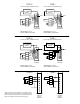
SWITCH CONVERTION FROM DIRECT TO INVERSE:
In order to change a Type “I” or Type “C” switch from direct operation to inverse operation, rotate the switch 180°
end-to end. For Type “C” switch, re-attach to bare wire. For Type “I” switch, re-tape to the bare wire.
TYPE “I” SWITCH TYPE “C” SWITCH
VOLTS
MAXIMUM CURRENT
AC DC
25 440mA 400mA
50 220mA 200mA
120 90mA 80mA
REED SWITCH RATINGS
DIRECT OPERATION
INVERSE OPERATION
DIRECT OPERATION
INVERSE OPERATION
S.G.
SUBTRACT FROM
LENGTH
S.G. ADD TO LENGTH
1.5 0.37 Inch 1.0 NONE
1.4 0.31 Inch 0.9 0.12 Inch
1.3 0.25 Inch 0.8 0.27 Inch
1.2 0.18 Inch 0.7 0.48 Inch
1.1 0.10 Inch *0.65 0.62 Inch
1.0 NONE *Recommended Minumum
SPECIFIC GRAVITY ADJUSTMENT