
Instruction Manual


6
1080 N. Crooks Road • Clawson, MI 48017 • 800.635.0289 • 248.435.0700 • Fax 248.435.8120 • www.AMETEKAPT.com
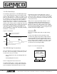
3.3 RS (Start/Stop)
The Start/Stop signal interface of the BRIK digital output
series is differential RS-422 output. The maximum cable
length for differential LDT's is 1,500 feet. To initiate a start
pulse, an external device is used. This start pulse should
be a minimum of 1.0 microsecond in duration. Within 50
nanoseconds after the leading edge of the start pulse,
the LDT will generate a start pulse of 1.0 microsecond in
duration. A stop pulse of 1.0 microsecond in duration will
follow. The time it takes from the leading edge of the start
pulse to the leading edge of the stop pulse is proportional
to the distance from the Null Zone to the Magnet . The
order of these two pulses is illustrated in Figure 3-4. To
wire the 955D-RS, see Figure 3-6. For proper grounding
information, see Section 3.4.
Figure 3-4 955D-RS
Once the LDT has been installed, wiring connections can
be made. There are two groups of connections you will
need to make. They are as follows:
• Power Supply Connections (including ground and
shield)
• LDT Input/Output Connections
Power Supply/Ground Connections
The 955D standard cable is a 6 Pin, 12mm, Euro Style
cordset. It has 6 conductors of 24ga, with an aluminum/
polyester/aluminum foil with drain wire plus an overall
3.4 955D Wiring Connections
braid of tinned copper shield. Cable O.D. is .270. To
reduce electrical noise, the shield must be properly used.
Connect the cable’s shield to the controller system GND.
The connector shell on the probe is electrically connected
to the probe housing.
Always observe proper grounding techniques such as
single point grounding and isolating high voltage (i.e.
120/240 VAC) from low voltage (13.5-30 VDC cables).
Whenever possible, this cable should be run in conduit
by itself. The power supply common, the cable shield and
a good earth ground should be connected together at the
location of the power supply common.
WARNING
!
U
Do not route the BRIK output cable near high voltage
sources.
In order for the 955D to operate properly, the LDT’s
external power supply must provide a voltage between
+13.5 to +30 VDC. The power supply must be rated at
150mA minimum. The power supply should provide less
than 1% rippel and 10% regulations. (The power supply
should be dedicated to the LDT to prevent noise from
external loads from affecting the BRIK.)
INPUT (INTERROGATION PULSE)
1 MICROSECOND (RECOMMENDED)
0.2 MICROSECONDS (MINIMUM)
TIME BETWEEN PULSES IS PROPORTIONAL TO
DISTANCE BETWEEN MAGNET AND HEX HEAD
OUTPUT (START PULSE) OUTPUT (STOP PULSE)
WITHIN 50 NANOSECONDS AFTER INTERROGATION
PULSE, START PULSE BEGINS
TIME BETWEEN PULSES IS PROPORTIONAL TO
DISTANCE BETWEEN MAGNET AND NULL ZONE
UNIPOLAR
Single ended
power supply
+13.5 to +30 VDC
+ COM
Pin 1 (brown) Pin 3 (blue)
Figure 3.5 Power Supply Wiring