
Instruction Manual


7
1080 N. Crooks Road • Clawson, MI 48017 • 800.635.0289 • 248.435.0700 • Fax 248.435.8120 • www.AMETEKAPT.com
Part Number
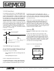
949-021LX (X = Length in Feet)
Shield
Cable Assembly
Part Number 949-021LX
(X = Length in Feet)
PIN - 1 BROWN
PIN - 6 PINK
PIN - 5 GRAY
PIN - 4 BLACK
PIN - 3 BLUE
PIN - 2 WHITE
POWER +
OUT +
INT+
INT-
OUT-
COMMON
Automatic Gain Control
The Automatic Gain Control feature will automatically
search and fi nd the magnet on power up, if power is
applied without a magnet on the LDT, the LED will turn
RED indicating no magnet signal is detected. Turn power
off and place magnet within the active stroke area. Re-
apply power.
When using the Floating Magnet assembly (SD0522100),
the magnet should be installed within 3/8” of the sensing
surface. The magnet assembly should also be installed
so that it remains an even distance from the aluminum
extrusion throughout the entire stroke. Improperly
installed magnets can result in output signal non-linearity.
LED Colors
Green Magnet is present and within the active programmed
range.
Red Fault, the LDT has lost its signal from the magnet or the
magnet has moved into the Null Zone or Dead Band.
Yellow No external interrogation signal detected.
3.5 Features
Figure 3.6 Wiring Diagram