MODEL S-101 EYELET BUTTONHOLE MACHINE PARTS AND SERVICE MANUAL PART NUMBER 97. 1000.0.003 AMF is trademark of AMF Group, Inc.
Warranty Registration Card (Please Fax or Mail immediately after installation) Note: All Warranty Claims Void, unless Registration Card on file at AMF Reece HQ Machine model number: (S101, S100, S104, S105, S211, Decostitch, S4000 BH,EBS Mark II, etc) Manufacturer‘s serial or production number: Installation Site Information: Customer‘s Name: Customer‘s Mailing Address: Customer‘s Telephone Number: Supervising Mechanic‘s or Technician‘s Name: Signature of Supervising Technician: AMF Reece Technician‘s Nam
LIMITED WARRANTY ON NEW AMF REECE EQUIPMENT Warranty provisions: A ninety (90) day limited service labor warranty to correct defects in installation, workmanship, or material without charge for labor. This portion of the warranty applies to machines sold as ”installed” only. A one (1) year limited material warranty on major component parts to replace materials with defects. Any new part believed defective must be returned freight prepaid to AMF Reece, Inc. for inspection.
S-101 1-10 Revised 09/2004 e-mail: service@amfreece.cz; parts@amfreece.cz; website: www.amfreece.
S-101 CONTENTS SHEET NO. INSTRUCTION FOR INSTALLATION ON REECE INDIVIDUAL TABLES ............ 1-1 STOP MOTION ADJUSTMENTS ................................................................................... 1-2 MODEL 101 - SETTING UP INSTRUCTIONS .............................................................. 1-3 THREADING DIAGRAMS .............................................................................................. 1-4 MODEL 101 - OPERATING INSTRUCTIONS ............................................
S-101 CONTENTS CUT BEFORE - MACHINE ADJUSTMENTS ............................................................... 1-20 CORD TRIM Threading diamgrams ........................................................................................... 1-23 Upper thread draw-off and tension adjustments ................................................. 1-24 Thread pick-up adjustments ................................................................................. 1-24 Under thread draw-off and tension release ..........
S-101 EQUIMENT FAMILIARIZATION Description Eyelet Buttonhole Sewing Machine Up to 1,600 spm Stitch Type 401 two thread chainstitch Stitch Density 3 to 16 s/cm (7 to 40 spi) Buttonhole Lenght 13 to 32 mm ( 1/2" to 1 1/ 4") Automatic Cutting Lenght N/A Eze Shape (X; Y) mm No Eye; 2,7 x 4,3 X Sewing Speed Y End Shape flibar, open end Stitch Bite 2 to 4 mm Automatic Thread Triming AF - top thread only Lubrication Semi - automatic wicking system Electrical Supply 230V, 50/60Hz, 3 Ph 400V
S-101 INSTRUCTIONS FOR INSTALLATION ON REECE INDIVIDUAL TABLES Parts and Belting for this installation are contained in the accessory box which accompanies each machine. 1. Be certain that Motor Pulley rotates in direction of arrow. If not, motor rotation must be corrected before operating machine. 2. Check with a plumb line to see that the heel of Transmitter Pedal is 6“ in back of front edge of the table. 3. Place the Machine on the Table between the belt slots and even with front edge of Table.
S-101 STOP MOTION ADJUSTMENTS 101 Stop Position - all 101 models except the Eyelet and Cross Oval when the head of the machine is all the way forward. 1) Page 16, Figure 5 and 6 - Machine in stop position and the stitch wheel locked up. Check Roll 10.1122.0.000 ‘ on the 10.1120.0.000 Link. It should rest lightly on the 10.2018.1.000 ’ Length Gauge. Adjust by turning Adjustment Screw 10.2066.0.000 u on Bracket 10.1127.3.000. 2) Page 17, Figure 1A - Machine in stop position - locked up. Roll 01.
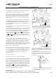
S-101 MODEL 101 - SETTING UP INSTRUCTIONS Before operating the machine by hand or power, remove the two shipping pins n shown Fig.1, which are easily identified by a red tag tied to each - these pins n are installed at the factory to lock the Head o and Bed Plate p together as a protection against shipping damages. Set up machine in accordance with the instructions on the installation template that is sent with each new machine.
S-101 THREADING DIAGRAMS UPPER SYSTEM Detail Thread is between tension discs Spread washer so that thread will rest in notch Detail Long groove Use T-20 thrading wire for threading needle bar THREADING OF FIXED TYPE TENSIONS Split disc type Solid roller type To needle bar To needle bar From thread supply From thread supply N o t e : Thread makes approximately one full turn around the roller on this tension.
S-101 THREADING DIAGRAMS LOWER SYSTEM Turn L.H. handwheel until race and loopers are in front. Thread as shown. Threading details for split disc tension CORD THREADING DIAGRAM Threading details for solid roller tension Throat plate Race Crank machine until race faces as shown. Note: Cord may also be led from rear of machine through guide A, and up through the race and throat plate as shown. Note: Refer to Sheet 23 for threading diagrams on Cord Trim Machines.
S-101 MODEL 101 - OPERATING INSTRUCTIONS 1. Remove the needle and test it for straightness, insert as below. Needle bar Needle holding screw Insert the needle as high as it will go (with long groove square with machine and on same side as is the tension disc). Tighten this screw securely! Tension discs 2. Put on the belts Caution! Before power is applied with foot treadle - see that needle bar is at its highest point - locked, and machine at its most forward position 3.
S-101 MODEL 101 - OPERATING INSTRUCTIONS Provision is made on this machine to meet any emergency arising during the making of the buttonhole. To extract work in case of unthreading or mislocation: Proceed as follows: 1. Press pedal on transmitter to stop belts. 2. Pull lever n in direction of arrow toward operator. 3. Turn R. H. handwheel (knurled rim) in direction of arrow until locked. 4. Move clamp lever o away from operator to release work - and withdraw it. 5.
S-101 ADJUSTMENTS THAT DETERMINE THE CHARACTER OF THE BUTTONHOLE NEEDLE INFORMATION Needles for the series 101 machine are available in a wide range of sizes and types as listed on sheet 30. As a general rule it is desirable to use needles with the finest blade that the thread and material will allow. On cut before machines it is particularly important to use fine, round pointed needles in the plain or spotted types.
S-101 ADJUSTMENTS THAT DETERMINE THE CHARACTER OFTHE BUTTONHOLE ADJUSTING THE BITE AND CUTTING SPACE B i t e - is the distance between the two points of entry of the needle into the fabric as it descends to make the stitch - character of material determines the width of bite Figure 1 Cutting space - it is space between the left and right bank of stitches into which the cutting knife descends to cut the material The ideal width of this space depends upon neatness required and character of material Thin fa
S-101 ADJUSTMENTS THAT DETERMINE THE CHARACTER OFTHE BUTTONHOLE ADJUSTING THE NUMBER OF STITCHES PER INCH IN A BUTTONHOLE Figure 1 Density of stitches or number of stitches per inch Loosen nut n and move lever assembly o in slot p, in either direction to suit. Movement in direction of rear of machine will decrease the number of stitches. Movement toward the front will increase the number.
S-101 MACHINE ADJUSTMENTS - CORRECTIVE AND MAINTENANCE NEEDLE BAR AND RACE LINE UP ADJUSTMENTS Adjustment # 3 Vibration in line with race adjustments. Adjustment # 2 For squareness of race east and west across bed plate. Adjustment # 1 For 180 o turn of race Adjustment # 4 It is imperative that the race swing east - west is only 180o (# 3). It is imperative that this 180 o be square with the center line of the bed plate (# 2).
S-101 MACHINE ADJUSTMENTS - CORRECTIVE AND MAINTENANCE EQUALIZING THE LOOPERS The loopers n and o when properly adjusted will assume the positions in Fig. 1 - with their points on center line of needle on alternate strokes after the needle bar has risen 3/32“ from its lowest position. To make this adjustment - remove the clamp plates - remove the throat plate from the race turn the machine with the L.H. handwheel (with handle) until the loopers are in front. Turn the R.H.
S-101 MACHINE ADJUSTMENTS - CORRECTIVE AND MAINTENANCE LOOPER AND SPREADER ADJUSTMENT I m p o r t a n t : Before making these adjustments, check adjustments of race Sheet 11 and for equalizing - Sheet 12 The loopers are held in place with the set screw n - if necessary loosen these screws and adjust the loopers so that there is a slight clearance (1/64“ of an inch) between them and the n needle when in positions shown in Fig.1. The spreader location is controlled by spreader stops.
S-101 MACHINE ADJUSTMENTS - CORRECTIVE AND MAINTENANCE TO ADJUST PLAY IN SPLIT COLLAR YOKE This yoke n must be adjusted to work smoothly but without excessibe play. Part o is a nut loosen screw p and screw up nut o to suit. n p o TO LINE UP AND ADJUST THE CUTTING LEVER u q q The cutting lever is suspended upon two adjustable studs q. Adjust these studs for centralization of cutting lever. To adjust cutting messure, turn nuts u inward for more pressure or outward for less.
S-101 MACHINE ADJUSTMENTS - CORRECTIVE AND MAINTENANCE To adjust the clamp plates parallel with ledge press the clamp plate firmly against the ledge of the bed plate with the hand - depress the clamp lever (101 - B 19) w. This will hold the clamp plate in position. Adjust the screw n firmly against edge o. Release the clamp lever - and screw n will be in adjustment.
S-101 MACHINE ADJUSTMENTS - CORRECTIVE AND MAINTENANCE TO ADJUST THE TRIP LEVER To equalize the ends of the stitching loosen nut n on stop screw o and screw in or out as required. o n TO CORRECT DISTORTION OF EYE Loosen nut p and move stud in slot of lever r until shape of eye is correct. r q p TO ADJUST THE ROLL PRESSURE ON LENGTH GAUGE Crank the machine until it is in the stopping position, turn the R.H. knurled stitch wheel until it is locked and wheel will not turn further.
S-101 MACHINE ADJUSTMENTS - CORRECTIVE AND MAINTENANCE TO ADJUST THE ROCKER ARM AND STOP MOTION Crank the machine with L.H. handwheel, to its stopping position. With the R.H. handwheel (knurled rim) turn until dog n is in contact with the stop bolt o - when in this position roller p should have a very light contact on low point of cam q on handwheel. Make adjustment by to suit. See note at bottom left of loosening screw r (Figure 3a) and swing rocking lever sheet. With the L.H.
S-101 MACHINE ADJUSTMENTS - CORRECTIVE AND MAINTENANCE ADJUSTING THE STOP LATCH ON STITCHING WHEEL p Note: Factory adjustment of this eccentric is made so that thick side of eccentric n v q is toward rear. This position must be maintained to prevent screw o from backing out. n t s v o r ADJUSTING THE TRIGGER SETTING MECHANISM Loosen screw o.
S-101 MACHINE ADJUSTMENTS - CORRECTIVE AND MAINTENANCE TO ADJUST L.H. HANDWHEEL TO DISENGAGE AT THE STOPPING POSITION OF THE MACHINE In this position contact points s and r should have a clearance about 1/64“ - if not: loosen nut n and move stud o in slot forward or back as required to obtain this clearance. Important: R.H. stop wheel (knurled rim) must be locked when making this adjustment TO ADJUST FOR FRICTION ON WORM SHAFT Loosen screw u on collar t.
S-101 CUT BEFORE - MACHINE ADJUSTMENTS Important: Before making the adjustments shown on this sheet, be sure the right hand stitch wheel is locked. VERTICAL SETTING OF TRIMMING KNIFE r o The trimming knife n (Figure 1) should be set so it will clear the under side of throat plate o at r and top of right hand spreader stop p at s to obtain this setting. Loosen screw q (Figure 1) and move trimming knife n up or down to suit. Tighten screw securely.
S-101 CUT BEFORE - MACHINE ADJUSTMENTS UPPER THREAD DRAW OFF (ROCKING TENSION TYPE) The amount of thread required to start the next buttonhole varies with the conditions and classes of work. Usually thin work requires more thread for starting purposes than heavy work. If more than one grade of work is passed thru the machine, it is desirable to make the adjustment on the lightest materials. Refer to sheets 4 and 5 for complete threading diagrams.
S-101 CUT BEFORE - MACHINE ADJUSTMENTS The amount of thread required to start the next buttonhole varies with the conditions and classes of work. Usually thin work requires more thread for starting purposes than heavy work. If more than one grade of work is passed thru the machine, it is desirable to make the adjustment on the lightest materials. To adjust for more or less thread - loosen nut p (Figure 1), and swing disc o in direction shown for the desired result.
S-101 CORD TRIM THREADING DIAGRAMS For tension threading details - see sheet 2 DETAIL CORD THREADING DIAGRAM See detail at right From cord supply Guide 1-24 Revised 09/2004 e-mail: service@amfreece.cz; parts@amfreece.cz; website: www.amfreece.
S-101 CORD TRIM - MACHINE ADJUSTMENT UPPER THREAD DRAW OFF AND TENSION ADJUSTMENTS Keep tension n tight enough to bread the upper thread at the last stitch. Make sure that lever o releases tension n when the machine starts sewing, so that only tension p will be effective during the sewing cycle. This tension should swing in the direction of arrow (Y) when the machine reaches the far end of its travel and in the direction of arrow (X) just before the machine stops.
S-101 CORD TRIM - MACHINE ADJUSTMENT THREAD TRIMMER AND THREAD RETAINER Upper thread trimmer is activated by a wedge located on the main cam. Movement of the thread trimmer should be delayed as late as possible to allow thread pick up hook to be in position, to pick up trimmed thread. Knife should be set to clear front of needle and bottom of throat plate. Also check that knife clears top of spreader. Knife should be installed and adjusted so that it trims thread on the return strock.
S-101 CORD TRIM - MACHINE ADJUSTMENT THEORY AND ADJUSTMENT TO INSURE PROPER FUNCTIONING OF CORD t t p p q s r n o To adjust for tension adjust spring s with screw r until there is sufficient friction on cord to lift weight upward to contact throat plate The excess end of the cord after the trimming must be pulled back with enough cord left in the throat plate to insure the proper start of another buttonhole - weight p on cord pull back serves to do this the drop of this cord.
S-101 ADJUSTMENTS FOR THE ADJUSTABLE FLY BAR MACHINE To adjust for length of buttonhole - loosen thumbscrew n and set gauge pointer to any graduation desired, and change cutting steel to conform. n o p To adjust length of fly bar - loosen screw o and adjust with lever p - swinging the lever entirely to the front will eliminate the fly bar. Range of adjustment is 0“ to 7/8“.
S-101 ADJUSTMENTS FOR THE ADJUSTABLE FLY BAR MACHINE u v n To adjust for proper functioning - tip the machine to a vertical position upon its base - crank the machine with the L.H. handwheel until the roll n is at the peak of the cam as shown. At this point plunger o must have enter slot p in cam plate q. If it does not enter freely and definitely - loosen screw r and tap head of machine s to suit. s p o t q r The above adjustment constututes the line up of an adjustable fly bar machine.
S-101 CUT BEFORE EDGING MACHINE UPPER THREAD DRAW-OFF AND TENSION DETAILS Keep Tension n tight enough to break the upper thread at the last stitch, and to prevent thread from being drawn from the source of supply through the needle as the gartment is removed from the machine. Make sure that Lever o releases Tension n when machine starts sewing, so that only Tension p will be effective during the sewing cycle.
S-101 NEEDLES Needles for the Reece Series 101 machines are packaged and sold in boxes of 100, in sizes and types listed. They are superior struck groove cosntruction, chrome plated and are spotted and the eye except size 00 and finer. When ordering, specify quantity .. (100, 200 etc.) and give the Needle E.D.P. Number. TYPE APPLICATION Applicable to the majority of women fabrics, ROUNU POINT knits and other materials of similar conLONG SHANK sistency.
S-101 COLOURED MARKING ON THE MACHINE COLOURED MARKING Screw - top links: Yellow marks — 1. Loosing and following disassembly of this link causes distinctive intervention to the mechanism adjustment, that was done when assembled and sewed off at the factory. 2. After such an intervention to the mechanism, new adjustment of set mechanism needs to be done and complete check of whole machine adjustment as well. Blue marks — Screws and nuts secured against loosing with glue ,,LOCTITE”.
S-101 LUBRICATION 1. Red marked places, pertinently the places with sticker with OIL description, must be regularly checker and lubricated, after every 30 hours of operating as of minimal. (More often when necessary.) 2. Let the machine cycle 20 times or more , so all excess oil can be removed. 3. Recommended lubricating oil TERESSTIC 68 Revised 09/2004 e-mail: service@amfreece.cz; parts@amfreece.cz ; website: www.amfreece.
S-101 1-34 Revised 09/2004 e-mail: service@amfreece.cz; parts@amfreece.cz; website: www.amfreece.
S-101 TROUBLESHOOTING TABLE OF CONTENTS Sheet TROUBLE DIGEST ............................................................................................................ 2-1 PRELIMINARY REMARKS ............................................................................................... 2-1 1. Machine fails to start ........................................................................................... 2-2 2. Machine started, ran a short distance and stopped ..........................................
S-101 TABLE OF CONTENTS TROUBLESHOOTING Sheet 22. Skipping at the start usually caused by the following ........................................... 2-7 23. Skipping at the junction of the Y of the tail bar .................................................. 2-7 24. Stitches raveling back at end of buttonhole ........................................................ 2-7 25. Breaking upper thread ...................................................................................... 2-7 26.
S-101 TROUBLESHOOTING TROUBLE DIGEST The object of this Digest is to make available to the users of Reece Series 101 buttonhole machines information that will aid them in locating troubles and the proper procedure to remedy them. PRELIMINARY REMARKS Reece Buttonhole Machines are of the fully automatic, heavy duty type for industrial use.
S-101 TROUBLESHOOTING The headings indicate the type of trouble. Below them will be found the probable cause for the trouble and its remedy. Machine failure as indicated by the heading can be traced to one or more of the causes beneath it. 1. MACHINE FAILS TO START: A) See that the Belts are on properly and power is applied. B) If Belts and Pulleys leading from Transmitter are not turning over, but the Center Pulley of the Transmitter is, there may be slipping in the Clutch. Adjust two Screws 01.
S-101 TROUBLESHOOTING 4. STITCHING OPERATION FAILS TO START OR HAS STARTED AND STOPPED: A) Right Hand Belt on wrong. B) Spring 01.5450 off or broken. REPLACE. C) Pin in Drive Cam 10.1095.3 broken. REPLACE Driver Cam 10.1095.3. D) Pivot of clutch 10.1089 not working freely in hole of Stop Wheel 10.1088.0.050. Smooth Pivot and clean hole in Stop Wheel. E) Pivot of Clutch 10.1089 broken. REPLACE. F) Set Screw in Feed Cam 10.1093 worked out. Screw in tightly. G) Spring 01.5088 on Trip Lever 10.1124 broken.
S-101 TROUBLESHOOTING E) Lever 10.1085 not functioning properly. Turn the Left Hand Crank Handle until Rocking Lever 10.1098.1.050 moves as far back as it will go and has slightly advanced. Adjust the Lever 10.1085 so that it will show a clearance between its end and the Dog 10.1102.1. When it is working properly the Lever 10.1085 will move up and down on the Cam of the Stop Wheel 10.1088 during the stitching operation and will prevent the forward motion of the Rocking Lever and Bolt 10.
S-101 TROUBLESHOOTING 13. MACHINE STITCHES A SHORT DISTANCE AND STOPS. THEN COMPLETES CYCLE: A) Trip Lever 10.1124 out of adjustment. Adjust according to instructions on Sheet 17, Fig. 3a. B) Trip Lever Spring 01.5088 broken. REPLACE. 14. CLAMPING AND UNCLAMPING: A) To raise Clamp Arms for more or less clearance. B) To raise Clamp Arms sooner or later. C) To apply more or less pressure on Clamp Arms. See Sheet 15, Fig. 2, for adjustment instructions. 15.
S-101 TROUBLESHOOTING E) Bevel sides of Cutting Steel 10.1069 (all) close to the cutting impression. F) Clamp spreading insufficient. Adjust for more spread - see Sheet 9, Fig. 4 G) When cutting of stitches takes place on both sides, give more space between right and left banks of stitches, according to instructions on Sheet 7, Fig. 2, 3. 20. DISTORTION OF EYE: A) Cord not drawing freely. Check source of trouble and eliminate. B) Hole in Throat Plate 10.4012 (all) too small. String out hole.
S-101 TROUBLESHOOTING O) Clamp Foot 10.2050.0.750 (to 755) and 10.2046.0.750 (to 755) too far away from outside needle stroke. Loosen Screws 01.2051 and adjust Clamp Blocks 10.2045 and 10.2049 inward to suit. P) Too much play in Looper Carrier 10.4002 (all). Adjusting Collar 10.4023 too loose. Adjust according to instructions on Sheet 14, Fig. 1. Q) Too much play in Looper Carrier 10.4002. Check up on worn parts or Rolls and replace. R) Clamp spread insufficient to take up slack in cloth.
S-101 TROUBLESHOOTING G) Prong of Left Spreader or end of Right Spreader too high or protruding over edge of Loopers. Spring downward, replace and reposition. See Sheet 13, Fig. 2, 3, 4 for adjustment. H) Needle striking Clamp Foot 10.2050.0.750 (to 755) or 10.2046.0.750 (to 755). Adjust by loosening Screw 01.2051 and move Clamp Arm outward to suit. I) Needle eye too small. REPLACE with a larger size Needle. J) Follow instructions under heading (21) “Skipping Stitches” from A to F. 26.
S-101 TROUBLESHOOTING 29. CHANGING CHARACTER OF BUTTONHOLE: A) To make the button hole even at the finish, adjust according to instructions on Sheet 16, Fig. 1, 2. B) To adjust length of buttonhole, see Sheet 8, Fig. 1, 2, for adjustment instructions. C) To increase or decrease the number of stitches in the entire buttonhole, see Sheet 10, Fig. 1 for instructions. D) To increase or decrease the number of stitches in the eye of buttonhole without affecting the sides, see Sheet 10, Fig. 2, for instructions.
S-101 TROUBLESHOOTING CORD TRIMMER This part of the Digest concerns the cord trimmer units and problems peculiar to the Cord Trimming Machine. Troubles on the basic part of this machine, where there is a similarity of parts and functions, should be looked up in the Digest on previous pages. Theory and Operation of the Trimming Function When the stitching of the buttonhole is completed, the Head and Cam Case move forward to cutting position.
S-101 TROUBLESHOOTING 1. END OF UPPER THREAD IS INSUFFICIENT FOR A PROPER START: A) Pick -up Hook 10.1207 missing the thread. Felt 10.1213 may need replacing. B) Burr on hook of Pick-up Hook 10.1207. Remove burr. C) Cutting Lever out of center. Centralize, see Sheet 14, Fig. 2 for adjustment instructions. D) Adjust Plate 10.1204 for more dip. See Sheet 24, Fig. 2, for adjustment instructions. E) Pick-up Hook 10.1207 broken. REPLACE. F) Upper Thread Draw-off out of adjustment See Sheet 24, Fig.
S-101 TROUBLESHOOTING 6. END OF CORD TOO SHORT: A) Adjust Stop 10.4220 upward according to instructions on Sheet 26, Fig.1 7. HOLD-DOWN FINGER 10.2212 NOT HOLDING WORK PROPERLY: A) Too much up and down play in Latch 10.2029. Tighten or REPLACE Screw 10.2030. B) Hold-down Finger 10.2212 bent upward. REPLACE or bend back to hold. 8. SHEARS NOT CUTTING: A) Dull. Stone edges. See Sheet 26, Fig. 3 for instructions. B) Not closing properly. Adjust according to instructions on Sheet 26, Fig. 4. C) Shear Blade 10.