
Service manual


e-mail: service@amfreece.cz; parts@amfreece.cz ; website: www.amfreece.com
Phones: +420 582 309 146 (Service), +420 582 309 286 (Spare Parts); Fax: +420 582 360 606
Revised 09/2004
S-101
1-3
101 Stop Position - all 101 models except the Eyelet and Cross Oval -
when the head of the machine is all the way forward.
1) Page 16, Figure 5 and 6 - Machine in stop position and the stitch
wheel locked up. Check Roll 10.1122.0.000 ‘ on the 10.1120.0.000
Link. It should rest lightly on the 10.2018.1.000 ’ Length Gauge.
Adjust by turning Adjustment Screw 10.2066.0.000 u on Bracket
10.1127.3.000.
2) Page 17, Figure 1A - Machine in stop position - locked up. Roll
01.7002 p should lightly contact the low point of the cam on the inside
of the Hand Wheel 10.1088.0.050. Adjust by loosening screw
10.1114.0.000 r on Three Forked Lever 10.1113.0.000 s. Recheck
adjustment number 1.
3) Page 18, Figures 4 and 5 - While holding turning pressure on
the Hand Wheel,
10.1088.0.050, crank the machine back by using the Cutting Wheel
10.3039.0.000 instead of the Crank 10.3037.1. (On Cut Before
machines, use the crank until after cutting or remove cutting steel.)
The 10.1089.0.000 Dog v on the 10.1088.0.000 Hand Wheel
should disengage the 10.1099.0.000 Bolt
on the Rocking Lever
as the 10.3038.1 Striker on the crank disengages the 10.3042.2
Dog on the cutting wheel. Adjust by loosening Clamp Screw
01.2035.0.000 on Shifter Spool 10.3045.0.000 and moving in or
out to suit.
4) Page 17, Figure 3-A - Crank the machine back until the
10.1122.0.000 Roll t is on the high point of the 10.2018 Length
Gauge u. In this position, the 10.1085.0.000 Lever should be
approximately 1/16“ from the 10.1102.0.000 Dog (not shown).
Adjust by loosening nut 10.3005 and positioning. Set the rise and
fall of the 10.1085 Lever so that its lowest point is approximately
1/16“ below the top of the 10.1102.0.000 Dog. Adjust by
positioning 10.1087.0.000 Bracket.
Check 10.1124.0.000 Lever w for correct clearance of Dog on the
Three Forked Lever (10.1113.0.000) - s by lifting 10.1118.0.000
Lever, which releases the 10.1120.0.000 Roll t and lets the
10.1124.0.000 w take over. The 10.1102.1.000 should not move
more than 2/3 of the distance to 10.1085.0.000. Adjust
10.1124.0.000 to suit.
5 & 6) Page 19, Figure 1.
5) Stop position 1/64“ between points (r and s).
6) Crank machine through cycle until 10.3039.0.000 Cutting Wheel
(Fig.1) shifts part way out as Lever w (10.1124.0.000, Fig. 3-A,
Page 17) is released. When one stitch more is taken by turning the
hand wheel, the cutting wheel shifts all the way out and the hand
wheel is locked up. Contact points at (r and s) should just clear
when the cutting wheel moves out. If hitting, adjust wheel inward
by loosening screw . Figure 5, Page 18 and tapping wheel.
Recheck adjustment 3. If compensation between these two
adjustments is not possible, the lower prong of the Three Forked
Lever has to be bent (removed from machine).
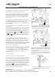
The full thickness .060“ (1/16“) is used to measure
the clearance between the end of the Flyover Lever
and the Rocking Lever Dog when the roll reaches
the highest point on the Length Gage.
Corner Step, 1/32“ measures distance between Dogs
on Cutting Wheel and Crank when machine is in
home locked position.
0.20“ Step at one end measures space between end of
Flyover Lever and Rocking Lever Dog when Three
Forked Lever is held by Trip Lever and Flyover Lever
is at its lowest point.
The Depth of the Step, .062“ measures the distance
that the lower tip of the Flyover Lever should be below
the top of the Rocking Lever Dog under the same
circumstances.
STOP MOTION ADJUSTMENTS