
User's Manual


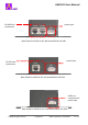


Table Of Contents

A9230-D User Manual
© AMIC All rights reserved Page9 of 21 AMIC Proprietary / Confidential
Rev 1.0C
3.3 Host Interface Cable Set ups
3.3.1 RS-485 Cable Interface for A9230-D-001-485 and
A9230-D-002-485 models
A typical RS-485 network consists of either two wires or four wires. A9230-D-001-485 and
A9230-D-002-485 RFID reader’s RS-485 interface uses RJ-45 type connector. Proper
wire connections should be made before inserting the cable into the RS-45 connector. It is
recommended that signal wire be twisted with ground wire as shown in the diagram below
to minimize noise and interference. Pin 8 (B) of the RJ-45 connector should be used for the
non-inverting RS-485 data signal. Pin 2 (O) of the RJ-45 connector should be used for the
inverting RS-485 data signal. Ground should be connected to Pin 7 (BW) and Pin 1 (OW)
of the RJ-45 connector.
O/W
O
G/W
G
B/W
BL/W
BL
B
Data+
Data-
GND
GND
GND
GND