OPERATING MANUAL CERAMIC PLATE WITH TOUCH CONTROL PG4VQ242 PBP4VQ242
DEAR USER, • • • • • • The Operating Manual has been compiled so that you may quickly yet thoroughly familiarise yourself with your new ceramic plate. Before using your ceramic plate for the first time, read this Operating Manual thoroughly and carefully. Familiarise yourself with your new appliance and its respective operating functions as they appear in the Manual.
TABLE OF CONTENTS Basic information.................................................................................................2 Safety instructions................................................................................................4 Saving energy.......................................................................................................5 Unpacking...............................................................................................................
SAFETY INSTRUCTIONS 4 Before using the ceramic plate for the first time read the Operating Manual carefully as thus you can ensure safe operation and avoid damage to the plate. If the ceramic plate is operated near a radio, TV set or other emitting device, please check whether the touch panel works correctly. The ceramic plate should be installed by a qualified electrician. Do not install the plate near refrigerating devices.
SAFETY INSTRUCTIONS Boiled over residuals of food may penetrate damaged places and get to the live components of the ceramic plate Should cracks or splits appear on the surface of your ceramic plate immediately disconnect it from the mains. In order to do so, switch off the fuse or pull out the mains plug from the socket. Call the Customer Service Please observe the maintenance and cleaning guidelines.
UNPACKING The appliance is protected from damage during transportation by its packaging. After unpacking please dispose of the packing materials in a manner creating no risk to the environment. All materials used for packing are harmless to the natural environment, can be recycled in 100% and have been identified with appropriate symbol. Caution! Packing materials (polyethylene bags, pieces of polystyrene etc.) should be kept away from children during unpacking.
DESCRIPTION OF THE APPLIANCE Description of PBP4VQ242 plate Hotplate – rear left 145 Hotplate – rear right 180 Hotplate – front left 210 Hotplate – front right 145 Control panel 3 2 2 Main sensor Hotplate selection sensor Hotplate indicators Minus sensor Plus sensor Lock sensor with LED signalling diode 5 4 1 1. 2. 3. 4. 5. 7.
INSTALLATION Installation of PBP4VQ242 plate prepare a place (an opening) in the table top according to dimensions specified on the installation drawing (Fig.
DESCRIPTION OF THE APPLIANCE Description of PG4VQ242 plate Hotplate – rear left 145 Hotplate – rear right 180 Hotplate – front left 210 Hotplate – front right 145 Control panel 3 2 2 Main sensor Hotplate selection sensor Hotplate indicators Minus sensor Plus sensor Lock sensor with LED signalling diode 5 4 1 1. 2. 3. 4. 5. 7.
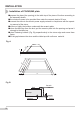
INSTALLATION Installation of PG4VQ242 plate prepare the place (the opening) in the table top of the piece of furniture according to the assembly sketch, the minimum space to be provided free under the ceramic plate is 80 mm, connect the stove to the electric power supply network in compliance with the operating manual of the stove, screw on lightly the holders underneath the ceramic plate, clean the table top from the dust, put the ceramic plate into the opening and press it strongly to the table
INSTALLATION Connecting the plate to the electrical system Note! The plate can be connected to the mains only by a qualified certified installer. Wilful adaptations or modifications to the electric system are prohibited. Guidelines for the installer The plate is factory-set for three-phase alternating current power supply (400 V 3N~50 Hz). It may be adapted for one-phase current power supply (230 V) by adequate bridging on the connection strip, in accordance with the attached wiring diagram.
INSTALLATION DIAGRAM OF POSSIBLE CONNECTIONS Warning! Heating elements voltage - 230V Warning! In every type of connection protective grounding has to be connected to PE terminal 1 Mains 230V one phase connection with neutral conductor, bridged terminals 1-2-3 and 4-5. Protecting grounding on 1/N~ 2 Mains 400/230V two phase connection with neural conductor, bridged terminals 2-3 and 4-5.
OPERATION The ceramic plate is equipped with sensors operated by touching the marked areas with a finger. Every touch of a sensor is confirmed with a sound. When switching the plate on and off and setting the heating power always touch only one sensor. If you touch several sensors at the same time (with the exception of switching off the hotplate or the clock), the system will ignore the entered settings and, should you keep touching the sensors for a long time, will emit a fault signal.
OPERATION Control panel Upon connecting the plate to the mains a short sound should be emitted, after which you can operate the plate! Caution! Do not put any objects on the area of the sensors (a fault can be trigged), always keep them clean. Switching on the ceramic plate If the plate is not in operation, all the hotplates are switched off and the display is blank. When you touch the main sensor (1), the plate switches on and all the hotplate indicators (3) show “0” for about 10 seconds.
OPERATION Setting up the heating power To set the required heating power first you have to select a hotplate with sensor (2). As long as digit “0“ is flashing on the indicator (3), you may set the required heating power with „+” (5) or „-” (4) sensors. If you do not wish to use the automatic power reduction system, start setting the heating power from „+” sensor (5). You may then increase the heating power with „+” sensor (5) or reduce it with „-” sensor (4).
OPERATION Switching off the whole ceramic plate The plate is in operation as long as at least one hotplate is switched on. You can switch off the whole plate by touching the main sensor (1). The hotplate indicator (3) displays letter “H”, indicating the residual temperature. Switching off a hotplate You can switch off one of the hotplates proceeding as follows: 1. Select the hotplate you wish to switch off with the hotplate selection sensor (2). 2.
OPERATION Residual temperature indicator When a hot plate has been switched off, letter “H” is displayed indicating that the hotplate is still hot. Do not touch the hotplate and do not put heat-sensitive objects on it when the “H” letter is displayed as you can burn yourself or melt the object! When the indication goes out you can touch the hotplate, bearing in mind that it still does not have ambient temperature. After power failure the residual temperature indicator is no longer active.
CLEANING AND ROUTINE MAINTENANCE Daily cleaning and proper maintenance have crucial impact on the durability of your ceramic plate. Clean the ceramic plate observing the same rules as for glass. Never use abrasive or aggressive cleaning agents, scrubbing powders or scratching sponges. Cleaning the plate after every use Wipe off slight, not-burnt patches of dirt using damp cloth without cleaning agent. Washing liquid can cause blue discoloration to appear on the plate.
CLEANING AND ROUTINE MAINTENANCE Never apply cleaning agent on a hot hotplate. Leave the cleaning agent to dry and then wipe it off with a wet cloth. Any residuals of cleaning agents should be wiped off with a damp cloth before heating the plate for the next time, as otherwise they can have caustic effect.
EMERGENCY PROCEDURES Every time when emergency situation occurs you should: • switch off the working assemblies of the plate • disconnect power supply • call in the service • as some minor faults can be removed by the user in accordance with the below specified instructions, before calling the Customer Service please go through the Table checking every point. PROBLEM CAUSE ACTION 1.The appliance is not wor- - Power supply failure king - Check the in-house fuse, replace if necessary 2.
EMERGENCY PROCEDURES PROBLEM CAUSE ACTION 7.Residual temperature indica- - Power supply failure, the -The residual temperature tor is not lighted although the appliance has been discon- indicator will work again after switching the control panel nected from the mains hotplates are still hot on and off. 8. Crack in the ceramic plate 9. If the fault still remains Danger! Immediately disconnect the ceramic plate from the mains (fuse) and call the nearest Customer Service Centre.
TECHNICAL DATA Rated voltage Rated power 3N 400V ~50 Hz Dimensions Weight 581 x 513 x 48; 575 x 505 x 48; ca.
WARRANTY AND POST-SALE SERVICES Warranty Warranty services according to the warranty card. The producer shall not be held liable for any damages caused by improper operation of the product. Please enter the type and factory number of the plate from the rating plate Type...................................... Factory number......................................
IOAA-232 (05.