
Technical data


12
OPERATION
INSTALLATION
Before first use
when used for the first time the plate can give off a bit of a smell so switch on the ventilation
system or open the window
operate the plate observing the safety instructions
carefully clean the ceramic plate treating it as a glass surface
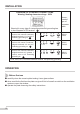
DIAGRAM OF POSSIBLE CONNECTIONS
Warning! Heating elements voltage - 230V
1
2
3
Mains 230V one phase con-
nection with neutral conductor,
bridged terminals 1-2-3 and 4-5.
Protecting grounding on
Mains 400/230V two phase con
-
nection with neural conductor,
bridged terminals 2-3 and 4-5.
Protecting grounding on
Mains 400/230V three phase con
-
nection with neutral conductor,
bridged terminals 4-5, phases 1,
2 and 3, zero on 4-5. Protecting
grounding on
1/N-
~
2/N-
~
3/N-
~
H05VV-
-F3G4
H05VV-
-F4G2,5
H05VV-
-F5G1,5
L1=R, L2=S, L3=T, N=neutral conductor terminal, PE=protecting grounding
Warning! In every type of connection protective grounding has
to be connected to PE terminal
Recom-
mended
type of
connector
cable
1
L1 N
2 43
PE
5
1
L1 L2
N
2 4
3
PE
5
1
L1 L2
N
2 4
3
PE
5
L3