Installation Instructions Adjustable Height Monitor (AHM) Arm w w w . a m i c o .
PREFACE Important, Please Read Carefully Thank you for your purchase with Amico. This unit is designed for long lasting performance, providing the end user complies with assembly and maintenance procedures. This Instruction Manual is your guide to ensure that you get the best performance out of the equipment.
Table of Contents Section 1: Installation Preparation Installation, Tools and Parts requirement Pre-Installation Information Typical Installation Reference AHM Section 2: Installation on Rail System Mounting to the MRS and OSHPD anchor Pre-Approval Mounting to the Hill-Rom Rail Mounting to the VRS and Ohmeda Rail Mounting to the ARS (Headwall) 1 2 3 4 5 6-7 8 Section 3: Installation of Monitor and Accessory Monitor Mounting: Monitor Shelf 3" and 5" Top and Back Mount Monitor Mounting: Monitor Shelf : 6’’
Section 1: Installation Preparations Installation Tools and Parts Requirements The table below lists all the tools and parts required for the installation.
Pre-Installation Information Please Read Carefully Before Starting WARNING: Verify that rails have been installed in accordance with Amico rail installation instructions. Rail failure with devices mounted can cause serious injury and equipment damage. WARNING: It is dangerous to use the arm for weights outside of the rated range. Structural failure and/or serious injury could result. WARNING: Never position the arm above a patient.
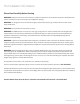
2. Monitor Head - Rotation (Pg. 22) Monitor Rotation Adjustment 3. Height Locking Lever (Pg. 25) Typical Installation Reference Locks the arm at a desired height 4. Counter Balance (Pg. 27) UsedThe todiagram adjustbelow for zero movement. illustrates the components referenced in relation to one another in the installation of the AHM Monitor Arm. Please follow the instructions 5. Extension Arm (Pg. 26) outlined herein to ensure proper installation. 6’’ extension arm shown 6.Mounting Adapter (Pg.
Section 2: Installation on Rail System Mounting to the Monitor Rail System (MRS) with the MON-Adapter WARNING: Never attempt to mount or remove the arm from the rail when a monitor is installed. WARNING: To prevent the adapter from falling down the channel, ensure that the 4 set screws are fastened to the tightest possible position (Figure 1). NOTE: For safety, top and bottom stoppers prevent the adapter from sliding out of the MRS.
Mounting to the Hill-Rom Rail (with the G-Track Adapter (GTA)) WARNING: To prevent the adapter from falling down the channel, ensure that the screws are secured to the tightest possible position. After installation, rotate the AHM arm side to side and verify no movement is present between the adapter and the rail. WARNING: Removal of lock nuts will require a new set for reinstallation. Please contact Amico Accessories for spare parts, 1-877-264-2697 1.
Mounting to the VRS (Vertical Rail System) and the Ohmeda Rail WARNING: Both adapters must be sitting in the rail securely. WARNING: To prevent the adapter from falling down the channel ensure that the screw knobs are fastened to the tightest possible position. After the installation, rotate the AHM arm side to side to verify that no movement is present between the adapters and the rail.
Mounting to the VRS (Vertical Rail System) and the Ohmeda Rail 1. Ensure the V-adapter (or the D-Adapter) is in the UNLOCKED position, and ensure the AHM arm is LOCKED in the highest vertical position. 2. Angle the adapters into the groove of the channel. Then straighten once inserted. (Figure 4 and 5) 3. Tighten screw knobs with a 3/16’’ Allen key when adapter is at desired height. Once tightened, the screw knob will protrude from the other side. Fasten the nut to the screw to secure the adapter.
Mounting to the ARS (Amico Rail System) WARNING: Never attempt to mount or remove the arm from the rail when a monitor is installed WARNING: Your AHM is pre-assembled with the ARS adapter(s), ensure that the ARS adapter is sitting inside the rail properly before installing a monitor. DO NOT install the AHM with just one adapter. Both ARS adapters must be installed. Only exception is if your unit is to be installed on a single ARS Rail.
Section 3: Installation to Monitor and Accessory Monitor Mounting WARNING: Ensure that the arm is in the highest position and is locked before mounting or removing the arm from the channel. WARNING: Ensure the monitor shelves/plates provided by Amico Accessories or other manufacturers are assembled as directed and match the shelf requirement.
Section 3: Installation to Monitor and Accessory Monitor Shelf: 3" Top/Back Mount, 5" Top/ Back Mount and VESA WARNING: Ensure the mounting shelf is securely locked and horizontal to prevent the monitor from sliding and falling. WARNING: On the bottom of the mounting shelf there is a plunger that secures the shelf to the mounting adapter. Simply pull down on the plunger, align the adapter plate with the shelf and release the plunger once positioned over the clearance hole.
Section 3: Installation to Monitor and Accessory Monitor Shelf: 6" Drop On WARNING: Ensure the mounting shelf is secure and locked in the vertical position to prevent the monitor from sliding and/or falling. NOTE: Quick installation system: On the back of the mounting plate there is a plunger that secures the plate to the mounting adapter. Simply slide and align the adapter to the shelf and the plunger will automatically engage and lock. 1.
Section 3: Installation to Monitor and Accessory Monitor Shelf: Philips Intellivue WARNING: Ensure the mounting shelf is firmly locked and horizontal to prevent the monitor from sliding and falling. NOTE: Philips recommends a Maximum tilt of 15 degrees NOTE: It is recommend to use M6 x 20 mm screws with thread locker or patched screws in order to eliminate possible dangers. 1.
Section 3: Installation to Monitor and Accessory Monitor Shelf: Welch Allyn WARNING: Ensure the mounting shelf is secure and horizontal to prevent the monitor from sliding and falling. 1. To attach the monitor to the Welch Allyn shelf, lift the monitor to match the front lip of the mounting plate. Slide the monitor laterally until the mounting hole on the monitor aligns with the thumb screw on the adapter. 2. Tighten the thumb screw by hand to the tightest possible position (Figure 2).
Section 3: Installation to Monitor and Accessory Monitor Shelf: VESA NOTE: Setting the VESA shelf horizontally can make the mounting procedure easier. NOTE: An adapter plate for the 5’’ shelf is available NOTE: If the original monitor bolts are too large, simply enlarge the mounting holes on the VESA Plate to fit. 1. Determine the monitor mounting configuration. VESA 75 (75 mm x 75 mm M4 thread) or VESA 100 (100 mm x 100 mm M4 threads) 2.
Section 3: Installation to Monitor and Accessory Accessory Shelf: Disc NOTE: It is possible to attach accessories to the top or bottom side of the AHM arm using this same mount (Figure 1). NOTE: Amico Accessories carries a variety of different accessories that attach to the head of the AHM Arm.
Section 4: Adjustments Rotation (AHM Side to Side) WARNING: In AHM with extensions, both arms have a 180 degree rotation. Ensure proper clearance around the arm(s) to avoid collision NOTE: If the arm becomes difficult to rotate, or too loose, please contact Amico Accessories: 1-877-264-2697 DETAIL 2 DETAIL 1 SCALE 1 : 4 SCALE 1 : 4 1 2 DETAIL 3 SCALE 1 : 4 3 Rotation at the MON Adapter: To rotate the arm, simply push on the side of the arm or the mounted monitor in the direction desired.
Section 4: Adjustments Monitor Tilt WARNING: Be sure to support the monitor if adjusting the tilt angle while the monitor is mounted. WARNING: For heavier monitors, it is strongly recommended to check whether the adjustment lever is tightened to the tightest position with the weight of the monitor attached. If the adjustment lever cannot be tightened enough to lock the monitor in place. Remove the Adjustment lever using a 4 mm Allen key, and use the 12 mm hex nut inside to adjust.
Section 4: Adjustments Rotation (Monitor Head Side to Side) WARNING: DO NOT adjust the rotation tension bolt. It will disassemble from the arm. If there are any problems associated with the monitor head please refer to the Troubleshooting section on pages 24-26, or contact Amico Accessories. (1-877-AMICO-XS) 1. The mounted device rotates at the front of the arm. To rotate the device, push the corners of the device or the head while holding the AHM in place.
Section 4: Adjustments Portrait and Landscape Limiter NOTE: Lock-out feature only available for monitors using VESA adapters NOTE: Lock-out is useful for shorter cables. It prohibits the rotation of the monitor to +/- 15 degrees. 1.
Section 4: Adjustments Attaching the Extension Arm NOTE: Extension arms are normally shipped assembled with the AHM arms. If the extension arm is not assembled, please follow the instructions below to attach the extension arm before mounting. 1.
Section 4: Adjustments Counter Balance WARNING: Do not over rotate the counter balance bolt. Once you feel a resistance, stop counter balancing. Forcing the bolt will damage the internals of the AHM arm and void the warranty. WARNING: Kick back motion: When the arm is locked and not in the highest position, it is capable of rapidly lifting to the highest position once the locking lever is released.
Section 4: Adjustments Counter Balance: Fail Safe Mode (Recommended for Applications Where No Possibility of Kick Back is Desired) WARNING: Please watch out for kick back motion of the AHM arm when releasing the locking lever. NOTE: Fail safe mode is set by counter balancing the arm without the weight of the monitor. In fail safe mode it will be harder to adjust the AHM arm vertically with the load. 1. Slide out the monitor and the adapter plate from the AHM arm. 2.
Section 4: Adjustments Cable Management: AHM Arm NOTE: A cable guide is provided to facilitate routing of cables along the bottom of the arm. NOTE: Longer cable guides are provided for arms with extensions. Guides also snap into grooves on the bottom of extension arms. 1. Squeeze the cable guide until its edges snap into the bottom surface grooves of the arm. If you encounter difficulty, you may use a flathead screwdriver to force the cable guide into the groove.
Section 5: Maintenance Troubleshooting and Product Classification Preventive Maintenance WARNING: AHM Arm require periodic inspection and maintenance to perform optimal and to achieve its maximum operation life. WARNING: The following schedule is a recommendation and not a strict schedule. Maintenance schedules should be shortened for AHM arms that see heavy use. Please be sure to thoroughly check the areas illustrated below for AHM arm. 1 2 3 4 5 6 www.amico.
Section 5: Maintenance Troubleshooting and Product Classification Area Maintenance Area 1: A) Check if the adapter plate and the monitor are securely attached. 1 • Mounting shelves and drop on shelf (AHM-XX (0, 2, 6, 8, and 9)) - Ensure the screws are tight. Ensure the plunger is securely holding the adapter. • VESA 75/100(AHM-LCD) - Ensure the four screws on the mounting plate are fastened to the tightest possible position.
Section 5: Maintenance Troubleshooting and Product Classification Troubleshooting Guide Symptom Possible Cause Please see “tilt” section of the manual (See page 17) or use an arm with a compatible • Weight of the monitor is not compatible rating with the arm • Too easy or too difficult to tilt the monitor up and down • Excessively loosened or tightened hardware. • Too easy or too difficult to twist the monitor left and right • Excessively loosened or tightened hardware.
Section 5: Maintenance Troubleshooting and Product Classification Cleaning WARNING: The cleaning chemicals and methods below are not meant for controlling any infections. It shall be the responsibility of the hospital or the hospital’s infection control officer to sanitize the equipment. WARNING: Please do not spray any chemical directly onto the arm. Apply onto a soft cloth and wipe clean to prevent chemicals getting into the insides of the arm.
AHM Arm Matrix AHM-XXY-(C)-(Z) 55 16” Extension Arm (406 mm) 15 12” Extension Arm (305 mm) 0 5” Shelf with 30° tilt limit 2 6" Drop on shelf 3 4 Philips IntelliVue with 30° tilt limit Accessory disc MON Standard Channel Adapter G Vertical Rail Adapter for Hill-Rom 35 9” Extension Arm (229 mm) 6 5" Shelf for back mounts 75 7 5” Shelf with slide-in VESA 75/100 Plate 6” Extension Arm (152 mm) 05 No extension V VRS adapter 8 3” Shelf with 30° tilt limit 9 3” Shelf for back mounts
AHM Arm Matrix AHM-LCD-XX-(C)-(Z) Standard Plates Provided VESA 75 55 16” Extension Arm (406 mm) Side View MON Standard Channel Adapter 15 12” Extension Arm (305 mm) G Vertical Rail Adapter for Hill-Rom VESA 100 35 9” Extension Arm (229 mm) 75 6” Extension Arm (152 mm) Side View V VRS adapter 05 No extension D Dovetail Rail adapter AHM-LCD-XX-(C)-(Z) C = Color of the AHM arm Black : C = B White : C = W 29 Amico Accessories
Accessories Warranty Policy Amico Accessories warrants all mounting accessories to be free from defects in material and workmanship for a period of twelve (12) months from the date of shipment. Within this period Amico Accessories will repair or replace any part which is proven to be defective. We don’t just send parts and pieces, we replace the product! Amico Accessories will warrant its material to be free from defect for an additional period of four (4) years, five (5) years from the date of shipment.
www.amico.com Amico Accessories | www.amico.com 85 Fulton Way, Richmond Hill Ontario, L4B 2N4, Canada 71 East Industry Court, Deer Park NY 11729, U.S.A Toll Free Tel: 1.877.264.2697 Toll Free Fax: 1.866.440.4986 Tel: 905.763.7778 Fax: 905.763.8587 Email: info@amico.