
Owner manual


3 Amico Accessories
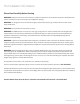
The diagram below illustrates the components referenced in relation to one another in the installation of the AHM
Monitor Arm. Please follow the instructions outlined herein to ensure proper installation.
Typical Installation Reference
AHM MONITOR ARM
1. Monitor Mounting Adapter
VESA LCD mount shown, other options available
2. Monitor Head - Rotation
Monitor Rotation Adjustment
3. Height Locking Lever
Locks the arm at a desired height
4. Counter Balance
Used to adjust for zero movement.
5. Extension Arm
6’’ extension arm shown
6. Mounting Adapter
MON adapter shown for MRS rail
7. Monitor Head - Tilt
Tilt Adjustment Handle
8. Cable Management
Manages the cables of the Monitor for better organization.
AHM MONITOR ARM
1. Monitor Mounting Adapter (Pg. 12-18)
VESA LCD mount shown, other options available
2. Monitor Head - Rotation (Pg. 22)
Monitor Rotation Adjustment
3. Height Locking Lever (Pg. 25)
Locks the arm at a desired height
4. Counter Balance (Pg. 27)
Used to adjust for zero movement.
5. Extension Arm (Pg. 26)
6’’ extension arm shown
6.Mounting Adapter (Pg. 6-10)
MON adapter shown for MRS rail
7. Monitor Head - Tilt (Pg. 21)
Tilt Adjustment Handle
8. Cable Management (Pg. 29)
Manages the cables of the Monitor
for better organization.
2
3
4
5
6
1
7
8