Source Equipment Air Compressors
Source Equipment Table of Contents 6.1 How To Use This Section..................................................................................................................................................................................................1 6.2 Introduction.............................................................................................................................................................................................................................1 6.2.
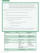
6.1 How to Use This Section The following section is structured in such a manner that the medical air system for a project may be established and executed in a sound and simple progression. Examples are given whenever possible. The basic milestones in designing the medical air system are as follows: • Definitions – Definitions are provided in the glossary section which contains terminologies which may be frequently utilized within the Medical Air Systems section.
6.3 Steps to Implementing the Medical Air Systems 6.3.1 Discovery 1. Should existing equipment is to be incorporated along with the Medical Air System, determine the dimensions, type, capacity and current loading of the existing equipment. Ensure the existing equipment is compatible with the current standard. 2. Verify the number and type of all occupancies in the facility which will require medical air outlets. 3.
. Determine a routing for the intake piping and note it on the building drawings. Piping downstream of the compressor shall be routed in a manner such that it is not subjected to temperatures lower than 4oC (40o F). 6. Ensure the intended location for the air plant is adequately ventilated or is at minimum air conditioned. The plant will emancipate considerable amount of heat into the surrounding.
SAMPLE SYSTEM SELECTION 1. Site conditions: A new hospital is being built, located in Vancouver, British Columbia with 298 medical air outlets. Space availability will be programmed based on system selection. The hospital is located 2 meters above sea level. Power and emergency generator system will be selected upon system selection. 2. Using Figure 2, an average PCL is determined. 3.
6.3.5 “Future Expansion” Compensation The notion of adding capacity now for any future requirements is wise, but extreme cautions are also advised. It is common to see very badly oversized air plants which were initially sized to accommodate an expansion that never occurred or that was scaled back and was not compulsory after all. In addition to the waste of investment, it generates problems associated with the operation of the system.
c. Check the size of the intake piping is still suitable at the new equivalent length. Should there be any discrepancies, re-estimate the next larger size and replicate the steps above. The line may also be sized more precisely by conducting an actual calculation. Intake piping must be sized to induce no more than 4inches water column vacuum at the compressor when all compressors are operating. (Use total capacity for this calculation with all compressors running).
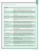
6.4 Medical Air Systems Glossary Definitions ACFM • Actual Cubic Feet per Minute is an expression of actual air volume, generally corrected for and reference to a particular pressure. ICFM • Conditions at the inlet of the compressor prior to any restrictions or temperature changes. (i.e., inlet filters, inter-coolers, discharge manifolds etc). Continuous Duty • Operational reference to compressors operating 24 hours a day, continuously.
6.4.1 Summary of CSA Specification of Division 15 (Air Compressors System) PART 1 – GENERAL (Medical Air) RELATED DOCUMENTS: Drawings and general provisions of the Contract, including general and supplementary conditions and Division I specification section, apply to this section. SUMMARY EXTENT OF WORK A.
OR if Owner will retain Verifier, use this paragraph; G. Coordinate with owner retained verifier for final verification of the systems. Make corrections as needed, including additional testing if necessary to illustrate full and unqualified certification. COORDINATION A. Medical Gas Contractor shall coordinate with other trades to ensure timely installations and evade conflicts and interference. B.
vi. Air filters including type and replacement element. vii. Pressure regulators including type and manufacturer. viii. Dew point monitor including technology employed calibration interval, and annual drift in degrees. ix. Carbon monoxide monitor including technology employed calibration interval, and annual drift in ppm. x. Air dryers, type, manufacturer, and design dew point at least -40˚C (-40˚ F) at 350 kPa (50 psig). xi.
3. Statement declaring that the MGEM has no fiduciary interest in the verifier and that the verifier is not an agent or representative of the MGEM. 4. Statement declaring that the installing contractor has no fiduciary interest in the verifier and that the verifier has no fiduciary interest in the contractor. C. Pre-approval 1. Written preapproval is required for equipment not exactly matching specifications.
D. 3. Warranties shall include on site repairs including travel, labor and parts. 4. Shipping and installation costs after the first 12 months will be borne by the customer. Verification: 1. Medical Gas Contractor shall deliver to the owner a complete system certification. PART 2 - PRODUCTS QUALIFICATION OF MANUFACTURER(S) A. One manufacturer shall supply all of the medical gas systems equipment, including the sources of supply.
6. The compressor modules and motors shall be fully isolated from the main compressor base by means of a four point; heavy-duty seismic restrained approved isolation system for a minimum of 95% isolation efficiency. Engineering data shall be provided supporting isolation efficiency and equal weight distribution between supports. Pumps not having this feature shall have an inertia base sized for that system installed at the contractors’ expense. 7.
2. Each compressor shall be equipped with an integral air-cooled after cooler designed for a maximum approach temperature of 7.0°C (15°F) ambient, a CRN certified moisture separator complete with electronic drain valve. 3. All required type “K” copper tubing or brass pipe to interconnect all compressor set components, with unions for ease of servicing. 4. Compressor motors shall be a NEMA rated, open drip proof unit with 1.15 service factor suitable for ______ Volt, ____ Phase, ___Hz.
e. f. Consideration shall be given to the potential effect of prevailing winds and possible sources of airborne contamination and potential for obstruction by accumulated snow. Piping downstream of the compressor shall be routed in such a way that it is not subjected to a temperature lower than 4˚C (40˚F). g. Piping and components shall be made of corrosive resistant materials such as brass, copper or stainless steel. D. Control Panel and Alarm Sensors The control system is C.U.L.
g. Visual/audible indications with isolated voltage free contacts for all alarm h. Event log recording of alarms and system activity i. Event log recording of service warnings and service history j. Trend graphs for compression level, compressor operations, and ambient temperature k. Adjustable settings to accommodate user needs 3. Panel designed with selectable options to fully match applications a.
E. Air Treatment Centre Provide redundant medical air treatment systems that contain CRN registered components including desiccant dryers, filters, and purifiers sized for peak calculated demand. Dew point and carbon monoxide monitoring Medical Air Treatment shall include: 1. Drying and purification units shall dry air to a dew point to -40°C at 350 kPa (-40°F at 50 psi). Refrigerant dryers are not acceptable. 2.
6.5 Quick Guide to Configuration Modular Stacking Configuration New “A-Frame”, modular stacking configuration allows two compressors to run simultaneously with smaller footprint and compact design. Compressor assemblies include at least one compressor and one motor. Horizontal Tank Mount The compressors are mounted on a horizontal tank which is large enough to accommodate bigger compressors and accessories than the Space Saver.
www.amico.
20 Amico Source Equipment
www.amico.
22 Amico Source Equipment
MODEL L A-SCD-D-120P-TH-C-075 A-SCD-D-080P-TH-C-075 A-SCD-D-120P-TH-C-050 A-SCD-D-080P-TH-C-050 A-SCD-D-080P-TH-C-030 A-SCD-D-080P-TH-C-020 RECEIVER DUPLEX CONTROL PANEL HMI MONITOR AIR COMPRESSOR ELECTRIC MOTOR 2 (1.49) 3 (2.24) 5 (3.73) 5 (3.73) 7.5 (5.60) 7.5 (5.60) HP (kW) 1 1 1 0.75 0.75 0.75 A INLET NPT TANK B SIZE OUTLET GALLON NPT (LITRE) 80G 0.5 (353) 80G 0.5 (353) 80G 0.5 (353) 120G 0.5 (529) 80G 0.75 (353) 120G 0.
24 Amico Source Equipment MODEL A-SCD-T-240P-SS-C-150 A-SCD-T-200P-SS-C-150 A-SCD-T-120P-SS-C-150 A-SCD-T-240P-SS-C-100 A-SCD-T-200P-SS-C-100 A-SCD-T-120P-SS-C-100 A-SCD-T-200P-SS-C-075 A-SCD-T-120P-SS-C-075 1/2 NPT DRAIN AT THE BACK OF THE RECEIVER TRIPLEX CONTROL PANEL HMI MONITOR 7.5 (5.60) 7.5 (5.60) 10 (7.46) 10 (7.46) 10 (7.46) 15 (11.2) 15 (11.2) 15 (11.2) HP (kW) L (16) HOLES 5/8" DIA. FOR ACHORING TO FLOOR A INLET CONNECTION B DISCHARGE CONNECTION 1.25 1.25 1.25 1 1 0.75 0.
1/2 NPT DRAIN AT THE BACK OF THE RECEIVER QUADRUPLEX CONTROL PANEL ELECTRIC MOTOR AIR COMPRESSOR A-SCD-Q-240P-SS-C-150 A-SCD-Q-200P-SS-C-150 A-SCD-Q-120P-SS-C-150 A-SCD-Q-240P-SS-C-100 A-SCD-Q-200P-SS-C-100 A-SCD-Q-120P-SS-C-100 A-SCD-Q-200P-SS-C-075 A-SCD-Q-120P-SS-C-075 MODEL RECEIVER A INLET CONNECTION 7.5 (5.60) 7.5 (5.60) 10 (7.46) 10 (7.46) 10 (7.46) 15 (11.2) 15 (11.2) 15 (11.2) HP (kW) L 1.25 1.25 1.25 1 1 0.75 0.75 0.75 A INLET NPT @ 50 psig 25.2 (713) 25.2 (713) 34.
26 Amico Source Equipment
www.amico.
28 Amico Source Equipment
30 Amico Source Equipment
32 Amico Source Equipment
www.amico.com Amico Source Equipment | www.amico.com 85 Fulton Way, Richmond Hill Ontario, L4B 2N4, Canada Toll Free Tel: 1.877.462.6426 Tel: 905.764.0800 Fax: 905.764.0862 Email: info@amico.