
Instruction Manual

5. Determine a routing for the intake piping and note it on the building drawings. Piping downstream of the
compressor shall be routed in a manner such that it is not subjected to temperatures lower than 4
o
C
(40
o
F).
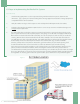
6. Ensure the intended location for the air plant is adequately ventilated or is at minimum air conditioned. The
plant will emancipate considerable amount of heat into the surrounding. Hence, it must be factored
in when selecting a compressor site; determining the adequacy of ventilation; or identifying BTU
requirements for air conditioning. (BTU data is furnished in the equipment data sheet).
7. Determine the availability of electrical service.
8. If the medical air system is not already piped to the proposed location, determine the routing for
the piping and note it on the building drawings.
6.3.2 Design
1. Follow directions for laying out piped medical gases. This will supply a count of outlets which is
necessary for the next steps.
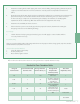
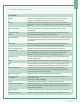
6.3.3 Plant Sizing
There are several available methods for sizing Medical Air. For the purpose of this design guide, only The Canadian
Standard Method (CSA) will be discussed.
The Canadian Standard Method
1. Count all outlets in the facility
2. Factor by facility size
3. Please refer to Figure 2 below
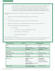
Figure 2: CSA Method - Medical Air Flow Calculation
Please refer to the table below to obtain an average ow that is required within the facility
www.amico.com
Medical Air Flow Calculation Table
Range of
Terminal Units
1-10 0 100
0
# of terminals x 25 L/
min x 100%
530 L/min + (25 L/min
x 50% x # of terminals
exceeding 25)
Total
11-25 0 75 0
26-100 0 50
0
>101
298 25 2704.5
2704.5 L/min
95.51 SCFM
250 L/min + (25 L/min
x 75% x # of terminals
exceeding 10)
1467 L/min + (25 L/
min x 25% x # of ter-
minals exceeding 100)
Actual Numbers Of
Terminal Units
Average Flow Per
Terminal Units (%)
Average Flow
Required Per
Terminal (L/min)
Total Flow
Required (L/min)
3