Installation Instructions MRS (Monitor Rail Systems) w w w . a m i c o .
Preface Important, Please Read Carefully Thank you for your purchase with Amico Accessories Inc. This unit is designed for long lasting performance, providing the end user complies with assembly and maintenance procedures. This Instruction Manual is your guide to ensure that you get the best performance out of the equipment. Amico Accessories Inc.
Table of Contents Section1: Product Specifications Features 3 Section 2: Installation Preparation Installation Tools and Parts Required 3 Pre-Installation Information (PLEASE READ CAREFULLY BEFORE STARTING) Section 3: Installation on Mounting Platform Channel Placement 4 5 Mounting on Drywall over Wood Studs or 16 Gauge Steel Studs 6 Mounting on Drywall over Steel Studs less than 16 Gauge 7 Section 4: Device Installation 7 Section 5: Maintenance, Troubleshooting and Product Classification Troub
Section 1: Product Specificaitons Features Amico Accessories Monitor Rail Systems are designed to accommodate all your monitor mounting needs. With durable Monitor Rail Systems, safe and reliable mounting supports are guaranteed for all facilities both vertically and horizontally. MRS (Monitor Rail System) 1. Typically used for mounting monitors 2. Built to handle vertical loads up to 60 lbs (27.21 kg) 3. Great for concealing cords and tubing 4. Designed for vertical or horizontal applications 5.
Section 2: Installation Preparation Pre-Installation Information (PLEASE READ CAREFULLY BEFORE STARTING) Although considerable effort has been made in this manual to ensure safety, the installation itself is beyond the control of Amico Accessories Inc. Accordingly, Amico Accessories Inc. will not be responsible for the failure of any such installation. WARNING: A lateral force of 80 lbs (36.287 kg) applied 17” (43.18 cm) out from the wall will crack a 5/8” (1.
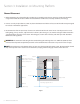
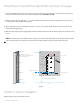
Section 3: Installation on Mounting Platform Channel Placement 1. Before mounting rail at desired height, consider the accessibility to the device controls including the allowable range of movement of the device when mounted. Built to handle vertical loads up to 60 lbs (27.2155 kg). 2. Devices can only be placed 0.75” (1.905 cm) above the bottom end of the rail because of the rubber stop. Designed for vertical or horizontal applications. 3. Recommend to allow 14” (35.
Mounting on Drywall Over Wood Studs or 16 Gauge Steel Studs 1. Locate the building studs in the area and align the holes of the rail to the studs. Use a level to make sure the rail is vertical and mark the locations on the wall through the holes centered on a stud. 2. Remove and put the rail aside. Drill 3/16” diameter holes into the wall at the marked locations. 3. Once all drill holes are completed, secure rail to the wall by fastening the screws through the holes and into studs.
Mounting on Drywall Over Steel Studs Less than 16 Gauge 1. Locate the building studs in the area and align the holes of the rail to the studs. Use a level to make sure the rail is vertical and mark the locations on the wall through the holes centered on a stud. 2. Remove and put the rail aside. Drill 11/16” (1.7462 cm) diameter holes into the wall at appropriate vertical spacing according to the specific MRS configuration. 3. Once all the drill holes are completed, insert the ¼-20 x 3” (7.
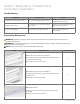
Section 5: Maintenance, Troubleshooting and Product Classification Troubleshooting Symptom Possible Cause Solution The depressible channel stop is loose. The screw securing the channel is loose. Tighten screw, if problem persists please contact Amico Accessories Inc. The rubber stop is loose. The mounting screw securing the rubber stop is loose. Tighten screw, if problem persists please contact Amico Accessories Inc. The rail is loose/unstable. The mounting screws have loosened.
Section 5: Maintenance, Troubleshooting and Product Classification Product Classification MRS-F____/ MRS-FL____/MRS-S____ Cleaning WARNING: The cleaning chemicals and methods below are not meant for controlling any infections. It shall be the responsibility of the hospital or the hospital’s infection control officer to sanitize the equipment. WARNING: Please do not spray any chemical directly onto the arm.
Accessories Warranty Policy Amico Accessories Inc. warrants all mounting accessories to be free from defects in material and workmanship for a period of twelve (12) months from the date of shipment. Within this period Amico Accessories Inc. will repair or replace any part which is proven to be defective. Amico Accessories Inc. will warrant its materials to be free from defect for an additional period of four (4) years, five (5) years from the date of shipment. Within this period, Amico Accessories Inc.
www.amico.com Amico Accessories Inc. | www.amico.com 85 Fulton Way, Richmond Hill Ontario, L4B 2N4, Canada 71 East Industry Court, Deer Park NY 11729, U.S.A Toll Free Tel: 1.877.264.2697 Toll Free Fax: 1.866.440.4986 Tel:905.763.7778 Fax:905.763.8587 Email: info@amico.com ACC MRS MANUAL 10.01.