Installation Instructions Falcon IT (FIT) w w w . a m i c o . c o m w w w . a m i c o .
Preface IMPORTANT, PLEASE READ CAREFULLY Thank you for your purchase with Amico Accessories Inc. This unit is designed for long lasting performance, providing the end user complies with assembly and maintenance procedures. This Instruction Manual is your guide to ensure that you get the best performance out of the equipment.
Contents Section 1: Installation Preparation Installation Tools Requirements Pre-Installation Information Typical Installation Reference FIT Station Section 2: Installation on Rail System Mounting to the MRS Rail OSHPD anchor Pre-Approval Mounting to the VRS/OHMEDA Rail Mounting to the ARS Rail Mounting to the G Rail Section 3: Device Installation Device Mounting Monitor: VESA 75 / 100 Mouse/Scanner Holder Keyboard and Mouse Wristpad and Mousepad Cable Management Independently mounted CPU All In One/CPU mou
SECTION 1: Installation Preparation Installation Tools Requirements The following table lists all the tools and parts required for installation Item Phillips screw driver #2 Item number A1 Qty 1 HEX keys (1/8” (0.3175cm), 3/16” (0.47625cm), M3, M4) A2 1 each A3 1 each A4 1 Socket wrenches (12 mm (1.2cm), ½” (0.05cm)) Adjustable wrench NOTE: Amico does not provide any monitor hardware, nor the tools necessary for assembly. A 1 2 3 4 4 Amico Accessories Inc.
SECTION 1: Installation Preparation Pre-Installation Information (Please Read Carefully Before Starting) WARNING VERIFY THAT RAILS HAVE BEEN INSTALLED IN ACCORDANCE WITH AMICO RAIL INSTALLATION IN STRUCT IONS. RAIL FAILURE WITH DEVICES MOUNTED CAN CAUSE SERIOUS INJURY AND EQUIPMENT DAMAGE WARNING IT IS DANGEROUS TO USE THE ARM FOR WEIGHTS OUTSIDE OF THE RATED RANGE. STRUCTURAL FAILURE AND/OR SERIOUS INJURY COULD RESULT WARNING DO NOT POSITION THE FIT STATION ABOVE A PATIENT.
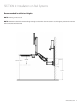
SECTION 1: Installation Preparation Typical Installation Reference The picture below illustrates the components referenced in relation to one another in the installation of the FIT STATION. Please follow the instructions outlined herein to ensure proper installation. FIT Station 1. Swivel Post (Pg.34) For mounting and positioning of monitor 2. Extension Arm (Pg.27) extension arm to increase movement range of AHM (if applicable) 3. Mounting Adapter(Pg.
SECTION 2: Installation on Rail Systems Recommended Installation Heights NOTE: Drawing is not to scale NOTE: CPU Mount should be mounted high enough so that when the FIT Station is at the highest position the monitor will not interfere with the CPU. 115.57 - 16.002 cm 44.45 cm 1.27 cm 88.9 cm www.amico.
SECTION 2: Installation on Rail Systems Mounting To The MRS (Monitor Rail System) FIT Station WARNING DO NOT attempt to mount/remove the FIT Station from the rail when loaded with any instrument WARNING DO NOT mount the FIT Station anywhere near or above a Patient’s head. WARNING To prevent the Mounting Adapter from sliding down the MRS, ensure the four set screws are fastened to the tightest possible position, serious injuries could result if the set screws are not properly fastened.
SECTION 2: Installation on Rail Systems CPU Mount WARNING Ensure CPU is within weight and size rating of the CPU mount. If not, please contact Amico Accessories at (1-877-264-2697) WARNING The CPU mount can be mounted anywhere at any height on the rail. However, DO NOT mount anywhere above a patient’s head. WARNING Ensure rail is stable and properly installed before mounting FIT Station. 1. Determine a suitable location on the MRS for the CPU to make sure it isn’t above a patient’s head. 2.
SECTION 2: Installation on Rail Systems Mounting To The VRS(Vertical Rail System) / Ohmeda Rail FIT Station WARNING All V-adapters must be sitting in the VRS securely. If not, serious injury could result. WARNING To prevent the V-adapter from falling down the VRS, ensure that the screws are fastened to the tightest possible position. After the installation, rotate the AHM arm side to side to verify that no movement is present between the adapters and the VRS.
SECTION 2: Installation on Rail Systems CPU Mount WARNING Ensure CPU is within weight and size rating of the CPU mount. If not, please contact Amico Accessories at (1-877-264-2697) WARNING The CPU mount can be mounted anywhere at any height on the rail. However, DO NOT mount anywhere above a patient’s head. WARNING Ensure rail is stable and properly installed before mounting FIT Station. 1. Determine a suitable location on the VRS for the CPU, making sure it isn’t above a patient’s head.
SECTION 2: Installation on Rail Systems Mounting To The ARS (Amico Rail System) FIT Station WARNING DO NOT attempt to mount/remove the FIT Station from the rail when loaded with any instrument WARNING DO NOT mount system anywhere near or above a Patient’s head. WARNING After the Mounting Adapters are installed, ensure that the levers on the Mounting Adapters are pressed in as far as possible and the adapters are sitting properly inside the rail before mounting devices.
SECTION 2: Installation on Rail Systems CPU Mount WARNING Ensure CPU is within weight and size rating of the CPU mount. If not, please contact Amico Accessories at (1-877-264-2697) WARNING After the Mounting Adapters are installed, ensure that the lever on the Mounting Adapters are pressed in as far as possible. WARNING The CPU mount can be mounted anywhere at any height on the rail. However, DO NOT mount anywhere above a patient’s head.
SECTION 2: Installation on Rail Systems Mounting To The Hill-Rom Vertical Rail FIT Station WARNING To prevent the Mounting Adapter from falling down the channel, ensure that the nuts are secured to the tightest possible position. After installation, rotate the AHM arm side to side and verify no movement is present between the adapter and the rail. WARNING Removal of lock nuts will require a new set for reinstallation.
SECTION 2: Installation on Rail Systems CPU Mount WARNING Ensure CPU is within weight and size rating of the CPU mount. If not, please contact Amico Accessories at (1-877-264-2697). WARNING Removal of lock nuts will require a new set for reinstallation. Please contact Amico Accessories for spare parts at (1-877-264-2697) WARNING The CPU mount can be mounted anywhere at any height on the rail. However, DO NOT mount anywhere above a patient’s head.
SECTION 3: Device Installation Monitor Mounting: VESA 75/100 WARNING Ensure that the AHM is in the highest vertical position and locked before mounting or removing devices from the FIT Station. NOTE See page 25 for instructions on locking and unlocking the AHM NOTE 4 x M4 screws are provided for mounting the monitor to the VESA Head, different screws may be needed if the provided screws are not the right size, standoffs may be needed depending on the hole pattern on the monitor. 1.
SECTION 3: Device Installation Mouse/Scanner Holder Installation WARNING Do not rest excessive weight on keyboard tray. It is rated for up to 15 lbs (7 kg) max. WARNING Ensure that the AHM is in the highest vertical position and locked before mounting or removing devices from the FIT. NOTE: See Page 25 for instructions on locking and unlocking the AHM The Keyboard tray comes with a mouse/scanner holder. The keyboard tray contains a sliding mouse tray as well as mousepads.
SECTION 3: Device Installation Keyboard and Mouse Mounting 1. Place keyboard onto the keyboard tray, place the mouse into the mouse holder, ensure the end with the cable faces up. Follow cable management procedures to route the cables through the FIT on page 19/22. NOTE: To secure the keyboard to a magnetic keyboard tray, place the magnetic keyboard onto the part of the tray with metallic inserts. 2.
SECTION 3: Device Installation Wrist Rest Mounting NOTE: Wrist rest is available but not provided with the FIT Station by default. 1. To secure the wrist rest to a keyboard tray, use the dual locking coins provided. Follow the instructions on the previous page to attach the twelve (12) dual locking coins to the wrist rest. 2.
SECTION 3: Device Installation Cable Management For Independently Mounted CPU Keyboard Tray Cable Management WARNING Do not bunch cables together on one tie. It may destroy the cable clips. Keep your cables in separate cable clips. Two cable clips are provided for use. NOTE: Ensure keyboard and mouse are both properly positioned as per the manual before beginning cable management procedures. (Figure 1) 1.
SECTION 3: Device Installation AHM Arm Cable Management NOTE: FIT cable guide is provided to facilitate routing of cables along the bottom of the arm. NOTE: Longer cable guides are provided for arms with extensions. Guides also snap into grooves on the bottom of extension arms. 1. Ensure devices are mounted, ensure keyboard tray and swivel post cable management is complete. Take the cables coming out of the keyboard tray and swivel post and press them between the openings of the cable cover (Figure 1). 2.
SECTION 3: Device Installation ARS Rail Cable Management NOTE: An ARS cable guide is available to facilitate routing of cables along the Rails and is not provided by default with the FIT Station. 1. Depending on where your CPU is mounted, guide the cables from the FIT station into the side of the channel leading to your CPU. (Figure 1) 2. Depending on where your electrical outlets are, guide the power cables from the FIT station into the side of the channel leading to your electrical outlets. (Figure 1) 3.
SECTION 3: Device Installation Cable Management For All In One/CPU Mounted At LCD Keyboard Tray Cable Management WARNING Do not bunch cables together on one tie. It may destroy the cable clips. Keep your cables in separate cable clips. Two cable clips are provided for use. NOTE: Ensure keyboard and mouse are both properly positioned as per the manual before beginning cable management procedures. 1.
SECTION 3: Device Installation AHM Arm Cable Management NOTE: FIT cable guide is provided to facilitate routing of cables along the bottom of the arm. NOTE: Longer cable guides are provided for arms with extensions. Guides also snap into grooves on the bottom of extension arms. 1. After installation of All in one/CPU, take the power cables and press them between the openings of the cable cover (Figure 1). 2. Ensure that there are at least 2” (5.
SECTION 3: Device Installation ARS Rail Cable Management NOTE: An ARS cable guide is available to facilitate routing of cables along the Rails. 1. Depending on where your electrical outlet is mounted, guide the cables from the FIT station into the side of the channel leading to your outlet. (Figure 1) 2. Guide the ARS rail cable cover into the channel over the cable. Ensuring no cable is pinched between the rail and the cover. Safely trim off any excess MRS cover after installation. (Figure 1) www.amico.
SECTION 4: Adjustments Height Locking Lever Adjustments: FIT Station WARNING The height locking lever must be installed properly before mounting the AHM to the rail or mounting the monitor to the AHM. WARNING Never attempt to move the arm vertically without loosening the lever. It will create excessive force on the AHM and may lead to premature failure. NOTE: The height locking lever is designed to inhibit all vertical movement of the AHM when it is in use.
SECTION 4: Adjustments Counterbalance: FIT Station WARNING Do not over-rotate the counterbalance bolt. Once you feel a resistance, stop. Forcing the bolt will damage the internal of the AHM and void the warranty. WARNING AHM back cover must be aligned with the counterbalance bolt and must be level. NOTE: The height locking lever must be engaged while adjusting the counterbalance. NOTE: Only adjust if necessary.
SECTION 4: Adjustments Installing The Extension Arm: NOTE: Extension arms are normally shipped assembled with the AHM. If the extension arm is not assembled, please follow the instructions below to attach the extension arm before mounting. WARNING Remove all mounted devices before removing the FIT station from the rail. WARNING Do not reuse the removed screws to attach AHM arm base, contact Amico Accessories at (1-877-264-2697). Use part number H-HSCSP-1032-58. 1.
SECTION 4: Adjustments FIT Post Portrait and Landscape Adjustment WARNING Make the adjustments with the monitor securely mounted. NOTE: To adjust the orientation, turn the monitor (Figure 1). Do not twist/tangle wires. 1. The Portrait and Landscape adjustment is done by holding the monitor and rotating 90 degrees. Portrait Landscape (Figure 1) www.amico.
SECTION 4: Adjustments Monitor Tilt & Swivel WARNING Be sure to support the monitor if adjusting the tilt angle with monitor mounted. WARNING After monitor is installed, tighten large and small tilt adjustment screws to tightest position possible with the weight of the monitor attached. Alternate between tightening large screw and small screw untill appropriate tension is reached. 1. The monitor can swivel 3600 (clockwise & counterclockwise/left & right) and also can tilt up & down by +/- 150.
SECTION 4: Adjustments Negative Tilt Knob NOTE: Negative Tilt knob is designed to tilt the BACK/REAR of the keyboard Tray down, and the FRONT of the keyboard upwards. WARNING Do not rest weight on keyboard tray while adjusting the negative tilt knob, doing so may deform keyboard arm. 1. To raise the angle of the keyboard, tilt the keyboard upwards until desired angle is achieved by hand, then turn the Negative Tilt knob clockwise until the knob cannot turn anymore. (Figure 1) 2.
SECTION 4: Adjustments System FIT Station Storage WARNING Remove all un-fixed equipment from the top of the keyboard tray before folding the FIT station WARNING Storing the FIT station with the height locking lever facing the wall may result in the lever hitting the wall. The lever may be removed before storage. NOTE: FIT Stations can easily be folded to free up floor space when not in use. NOTE: The following folding procedure assumes the FIT Station is in the default arm position.
SECTION 4: Adjustments 4. Rotate the arm towards the desired side of the channel. (Figure 1) 5. For a folding extension, hold the extension arm against the wall, and then pivot the AHM back towards the channel until it rotates another 180 degrees. (Figure 2) Caps Bolt (Figure 1) (Figure 2) 6. Rotational tension can be adjusted by tightening/loosening the bolts located at the joints of AHM/extension arms. Remove the caps to access the bolt before adjusting (Figure 1). www.amico.
SECTION 4: Adjustments Rotation WARNING For FIT Station with extension arms, both arms have a 180 degree rotation. Ensure proper clearance around the arm(s) to avoid collision. NOTE: If the arm becomes difficult to rotate, or too loose, please contact Amico Accessories: 1-877-264-2697 NOTE: Adjusting the rotational tension of the extension arms can be done by loosening or tightening the bolt at the joints of the arms and the adapter (Figure 1) using a 3/4” socket wrench or equivalent tool.
SECTION 4: Adjustments Swivel Post 1. The Swivel-post allows for vertical movement of the monitor independent of the keyboard tray and also allows for rotation of the monitor. 2. To rotate the keyboard tray with the monitor simply rotate the keyboard tray and the monitor will rotate along with it. 3. To rotate the monitor independently of the keyboard tray, hold the keyboard tray in place and rotate the monitor. VESA plate Swivel-Post Swivel Post Cable Cover Swivel (Figure 1) (Figure 2) www.amico.
SECTION 4: Adjustments Spring Adjustment WARNING Swivel-Post interior contains sharp edges, wear protective equiment when performing the tasks below. 1. The spring in the Swivel-Post can be replaced if the monitor weight changes in order to maintain the appropriate counterbalancing. 2. Remove the cap on top of the Swivel-Post to reveal the two screws. Use a philips head screwdriver (#2) to remove the two screws (Figure 1). Also remove the Swivel-Post cover. 3.
SECTION 5: Troubleshooting, Maintenance, Product Classification Troubleshooting Symptom Possible cause Solution - Too easy or too difficult to tilt the monitor up and down - Excessively loosened or tightened hardware. - Too easy or too difficult to utilize the portrait landscape feature - Damaged hardware. Please contact Amico Accessories. - Too easy or too difficult to rotate the monitor at the head left and right - Excessively loosened or tightened hardware.
SECTION 5: Troubleshooting, Maintenance, Product Classification Preventive Maintenance (FIT Station) WARNING: FIT stations require periodic inspection and maintenance to perform optimally and achieve maximum operation life. WARNING: The intervals shown on the next page are recommended. Maintenance schedules should be more frequent for higher use areas.
SECTION 5: Troubleshooting, Maintenance, Product Classification Area Period Maintenance (Month) Area 1: VESA Adapter 1 A) Check if the adapter plate and the monitor are securely attached. VESA 75/100 (FIT) Ensure the four screws on the mounting plate(s) are fastened to the tightest possible position. 4 1 B) Visually inspect for any signs of grinding and gapping. Area 2: Swivel Post 2 A) Inspect the bolt, washers and contacting surfaces for grinding and wearing.
SECTION 5: Troubleshooting, Maintenance, Product Classification AHM-FIT - - - Track Adapter Color W White X M Custom Monitor Channel Keyboard Tray Spring Strength 25 5.5-8 lbs (2.5-3.6 kg) Monitors F AB 35 Falcon *Amico Horizontal Direct Mount - Bottom 7.5-10 lbs (3.4-4.5 kg) Monitors 50 M 13-15.5 lbs (5.8-7 kg) Monitors Mini 60** 15.5-18 lbs (5.8-7 kg) Monitors XX X Custom (For Monitors > 18 lbs (7-8.
SECTION 5: Troubleshooting, Maintenance, Product Classification Cleaning WARNING: The cleaning chemicals and methods below are not meant for controlling any infections. It shall be the responsibility of the hospital or the hospital’s infection control officer to sanitize the equipment. WARNING: Please do not spray any chemical directly onto the arm. Apply onto a soft cloth and wipe clean to prevent chemicals getting into the internal components of the arm.
Accessories Warranty Policy Amico Accessories Inc. warrants all mounting accessories to be free from defects in material and workmanship for a period of twelve (12) months from the date of shipment. Within this period Amico Accessories Inc. will repair or replace any part which is proven to be defective. Amico Accessories Inc. will warrant its materials to be free from defect for an additional period of four (4) years, five (5) years from the date of shipment. Within this period, Amico Accessories Inc.
www.amico.com Amico Accessories Inc. | www.amico.com 85 Fulton Way, Richmond Hill Ontario, L4B 2N4, Canada 71 East Industry Court, Deer Park NY 11729, U.S.A Toll Free Tel: 1.877.264.2697 Toll Free Fax: 1.866.440.4986 Tel: 905.763.7778 Fax: 905.763.8587 Email: info@amico.com ACC FIT MANUAL Rev C 16.09.