
User's Manual

List of Figures
Version 0.4
AMIMON Confidential vi
List of Figures
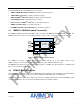
Figure 1: AMN11310 Block Diagram......................................................................................................................... 3
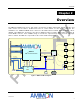
Figure 2: WHDI Baseband Transmitter Chipset........................................................................................................ 4
Figure 3: Video Data Processing Path ...................................................................................................................... 7
Figure 4: Timing Diagram.......................................................................................................................................... 9
Figure 5: I
2
S Simple System Configurations and Basic Interface Timing ............................................................... 10
Figure 6: I
2
S Input Timings ...................................................................................................................................... 11
Figure 7: Two-Wire Application/MAC Connection................................................................................................... 12
Figure 8: Two-Wire MAC Write Commands............................................................................................................ 13
Figure 9: Two-Wire Read Command....................................................................................................................... 13
Figure 10: Reset Time Diagram .............................................................................................................................. 14
Figure 11: Reset Mechanism .................................................................................................................................. 15
Figure 12: WHDI Connector .................................................................................................................................... 18
Figure 13: Mechanical Dimensions Top View ......................................................................................................... 27
Figure 14: Mechanical Dimensions Bottom View.................................................................................................... 28
Figure 15: RF-Shield Frame.................................................................................................................................... 29
Figure 16: RF-Shield Cover..................................................................................................................................... 30
List of Tables
Table 1: Common Supported Video Input Resolutions ............................................................................................. 8
Table 2: Video Channel Mapping .............................................................................................................................. 8
Table 3: Video Interface ............................................................................................................................................ 8
Table 4: I2S Audio Interface Timing Requirements ................................................................................................ 10
Table 5: Audio Interface Timing Requirements....................................................................................................... 11
Table 6: Device Addresses ..................................................................................................................................... 12
Table 7: Reset Timing Requirements...................................................................................................................... 15
Table 8: WHDI Connector Signals .......................................................................................................................... 17
Table 9: Tx WHDI Connector Pin List ..................................................................................................................... 19
Table 10: Absolute Maximum Ratings over Operating Case Temperature Range................................................. 21
Table 11: Recommended Operating Conditions ..................................................................................................... 21
Table 12: Electrical Characteristics over Recommended Range of Supply Voltage and Operating Conditions .... 21
Table 13: Digital Layout Recommendation ............................................................................................................. 23